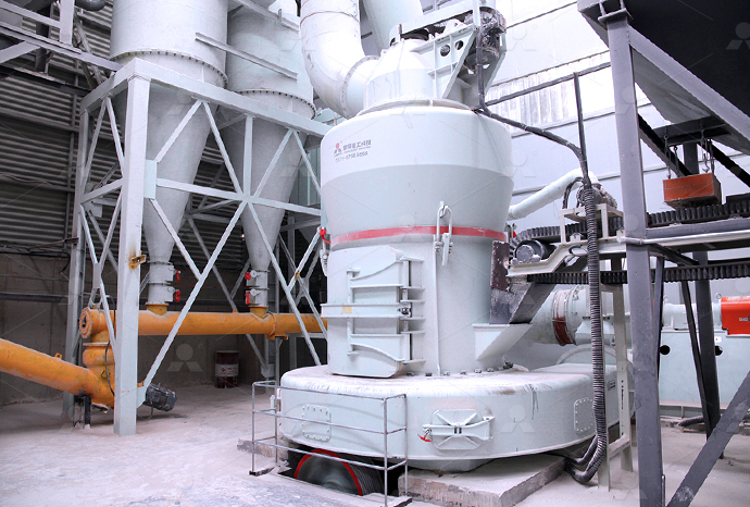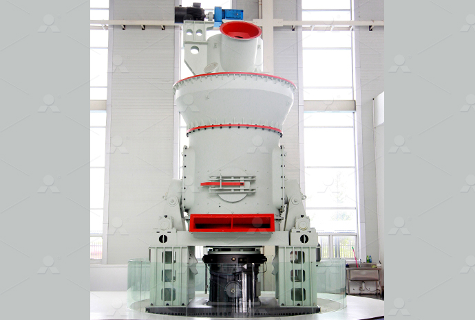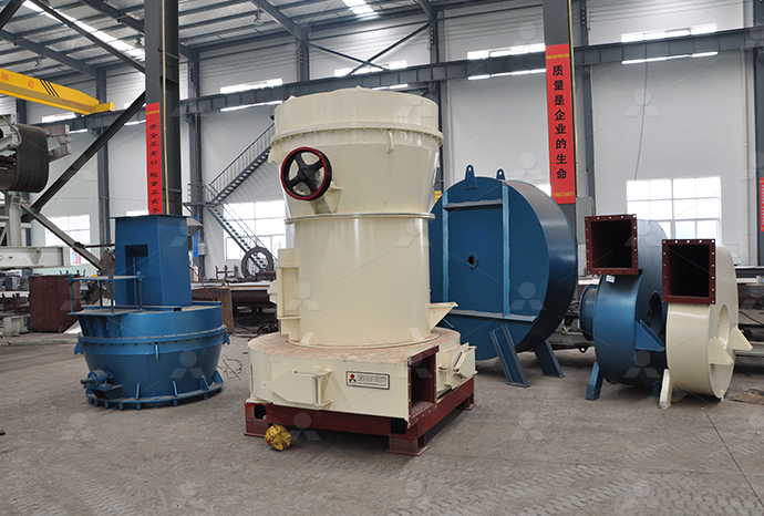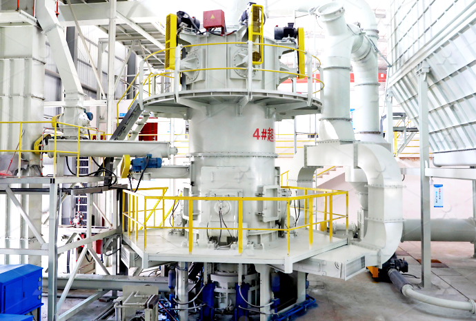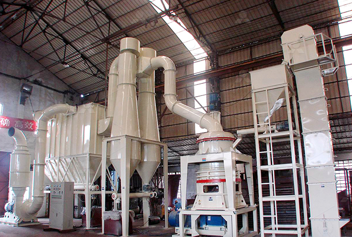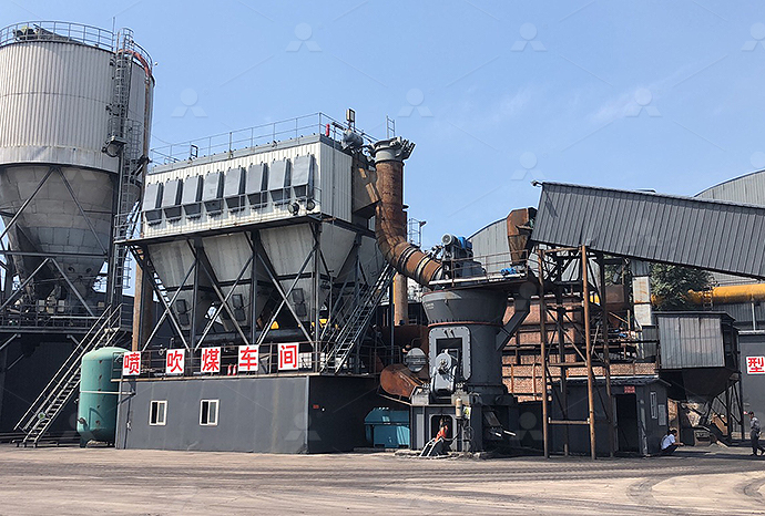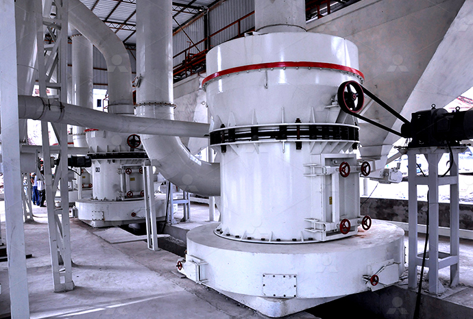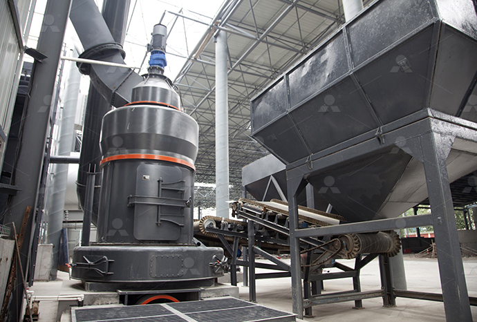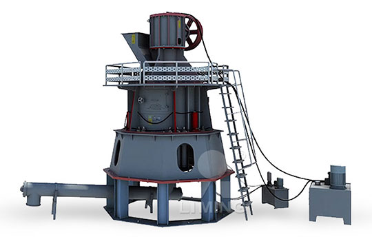
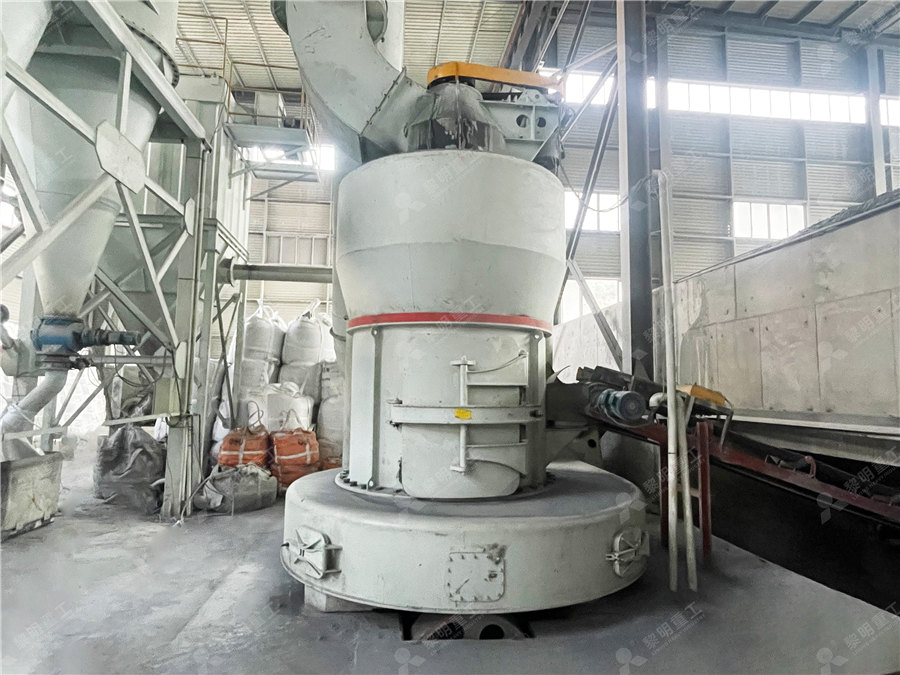
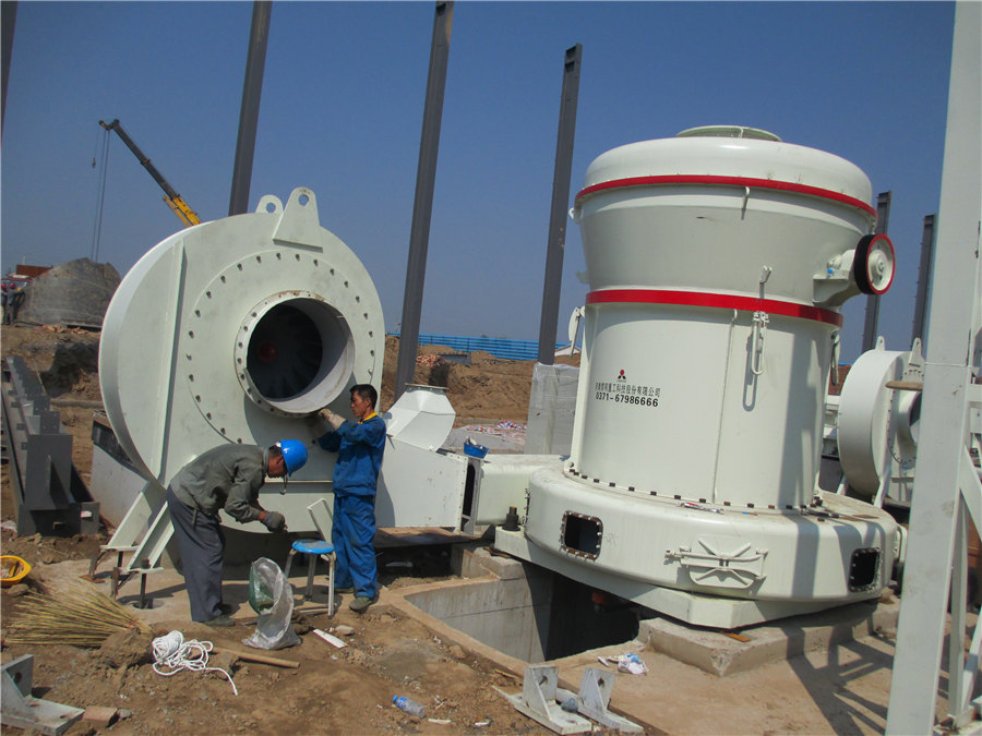
Hydraulic rock mill structure diagram
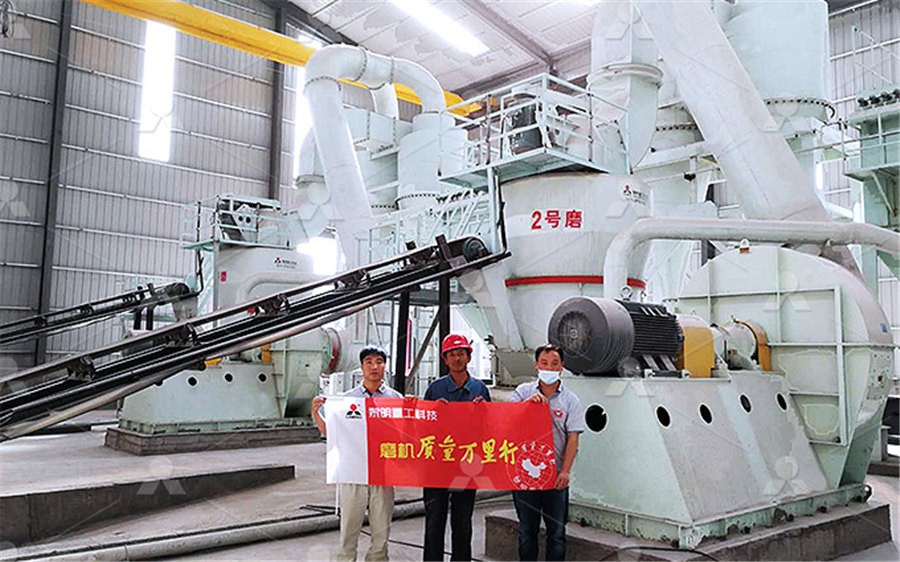
HYDRAULIC ROCK BREAKER OPERATING, MAINTENANCE
When breaker is used continuously, temperature of hydraulic oil converges at a certain level depending on conditions of environment and carrier At this temperature, the viscosity of the The basic structure of the roller mill includes the grinding roller, the grinding body, the force generation and transmission mechanism, airflow, and the device for easy replacement It can Roller Mill Springer2020年12月24日 Schematic diagram of a rock crusher: 1 Blake jaw crusher, 2 rock conveyor, 3 hydraulic boom manipulator Figure 2 shows a schematic diagram of the solution for mounting (PDF) Hydraulic Control System ResearchGateIn this article the AGC (Automated Gauge Control) system, of a hot rolling mill is analyzed and different methods are described to improve its performanceSchematic structure of a hot rolling mill Download Scientific
.jpg)
Operation Manual: HRM1700M Vertical Roller Coal Mill
It describes the mill's technical parameters, components, structure, working principles, and installation process Key aspects include grinding rollers that can be removed for 2015年3月25日 The hydraulic system of vertical mill is an important system, the main function of the hydraulic system is to break the grinding roller, which is when the internal grinding cavity Hydraulic system vertical roller mill operation PDF SlideShareSeveral iterations of the ALC were tuned and tested in fragmented rock pilessimilar to those found in operating minesby using both a robotic 1tonne capacity Kubota R520S diesel 1: Schematic drawing of the loadhauldump (LHD) machineInformation about crushing technology, construction, working and maintenance of crushers for bulk materials is given in this article There are four basic ways to reduce size of a material: by Construction, Working and Maintenance of Crushers for Crushing
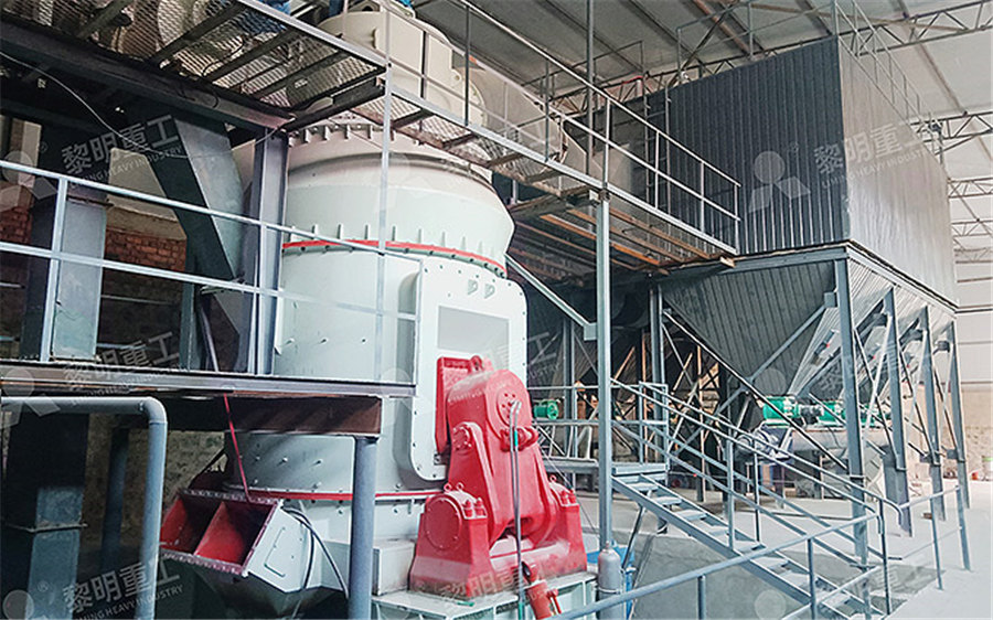
Jaw Crusher Diagram: Simplified Guide JXSC
2024年2月18日 Hydraulic Systems: Facilitate automatic adjustments and safety features like clearing jams Modern crushers may include hydraulic toggle adjustment for easy CSS 2024年3月19日 A cone crusher diagram shows the main parts of the machine These include the crushing shell, eccentric shaft, adjustment ring, and bottom shell The bottom shell is made Cone Crusher Diagram: Simplified Guide JXSCFigure 122: Hydraulic system pictorial diagram Cutaway Diagrams Cutaway diagrams (Figure 123) show the internal working parts of all fluid power components in a system The diagrams include controls and actuating Basic Diagrams and Systems Engineering Library2024年3月19日 Understand cone crusher diagram basics with our comprehensive blog post Learn about the structure and operation of cone crusher models Equipment An electric motor and belt pulley system power Cone Crusher Diagram: Simplified Guide JXSC
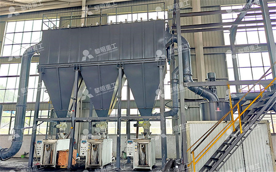
Fuzzy PID controller structure diagram ResearchGate
Download scientific diagram Fuzzy PID controller structure diagram from publication: Modeling and Research of Fuzzy PID Control Strategy for Hydraulic Rock Drill Propulsion System According to Use of hydraulic breaker or drum cutter is more economical, than use of a drill rig and explosives Rock structure (geology) Heavily fissured rock sometimes makes it difficult to drill and blast Selective mining To improve rock material quality and mineral purity the deposit layers could be excavated depending on the desired rock material qualityHydraulic attachment tools in surface rock excavationDownload scientific diagram The coupling model between improved hydraulic support and surrounding rock from publication: Dynamic model analysis of hydraulic support In view of the The coupling model between improved hydraulic support and surrounding rockDownload scientific diagram Schematic of the hydraulic breaker: (a) isometric view, (b) cross section A–A′ from publication: Estimation of Impact Loads in a Hydraulic Breaker by Transfer Schematic of the hydraulic breaker: (a) isometric view, (b) cross
.jpg)
Specific energy of crushing of various rock types
Download scientific diagram Specific energy of crushing of various rock types from publication: Impact of rock hardness on fragmentation by hydraulic hammerand crushing in jaw crusher The Download scientific diagram Schematic diagram of the mill structure from publication: Dynamic Model of the Hot Strip Rolling Mill Vibration Resulting from Entry Thickness Deviation and Its Schematic diagram of the mill structure ResearchGateDownload scientific diagram Structure diagram of fourhigh load roll system from publication: Absolute Stability Condition Derivation for Position ClosedLoop System in Hydraulic Automatic Structure diagram of fourhigh load roll systemDownload scientific diagram Structure diagram of a doubleacting singlepiston servo hydraulic cylinder from publication: Coupled Vibration Behavior of Hot Rolling Mill Rolls under Structure diagram of a doubleacting singlepiston servo hydraulic
.jpg)
Design, construction, and preliminary hydraulic
2023年8月7日 All content in this area was uploaded by Ryan Fitzpatrick on Aug 08, 2023PDF On Oct 23, 2022, Qiang Zhang and others published Studies on the performance of impact resistant structure of hydraulic support in fully mechanized mining face under rock burst Find, read Studies on the performance of impact resistant Download scientific diagram Principles of the hydraulic control system of the Rautaruukki hot rolling mill from publication: Intelligent Techniques for Condition Monitoring of Rolling Mill Principles of the hydraulic control system of the Download scientific diagram Structure model of double damping system from publication: Cavitation erosion of the damping piston in double damping system of hydraulic rock drill and its Structure model of double damping system Download Scientific Diagram
.jpg)
Schematic diagram of a rock crusher: 1 Blake jaw crusher, 2 rock
Download scientific diagram Schematic diagram of a rock crusher: 1 Blake jaw crusher, 2 rock conveyor, 3 hydraulic boom manipulator Figure 2 shows a schematic diagram of the solution for Download scientific diagram Structure diagram of the rotary drilling rig from publication: Transient Analysis of Rotary Drilling Rig in Response to Sudden Breaking of Wire Rope for Drilling Structure diagram of the rotary drilling rigDownload scientific diagram Hydraulic structural schematic diagram 1, Oil tank; 2, variable pump; 3, electrohydraulic proportional valve; 4, hydraulic lock; 5, combined cylinder; 6, balance Figure 2: Hydraulic structural schematic diagram 1, Oil tank; 2,2019年4月19日 Hydraulic rock drill, no constantpressuri zed chamber, per cussion characteristic, numerical simulation, fie ld rock drilling test Date received: 9 Octobe r 2018; accepted: 8 March 2019Percussion characteristic analysis for hydraulic rock drill with

REALISTIC ROCK WEIR HYDRAULICS THROUGH
Keywords: Rock weirs; realistic rock weir modeling; broadcrested weirs; numerical modeling 1 INTRODUCTION Channelspanning rock weirs are widely employed in rivers for purposes including fish passages, irrigation diversions, and floodplain reconnection, among many others Typical engineering design of rock weirs rely onA mill is a device, often a structure, machine or kitchen appliance, that breaks solid materials into smaller pieces by grinding, crushing, or cutting Such comminution is an important unit operation in many processesThere are many different types of mills and many types of materials processed in them Historically mills were powered by hand or by animals (eg, via a hand crank), Mill (grinding) Wikipedia2023年11月30日 Hydraulic rock breakers are powerful equipment that uses hydraulic pressure to easily break apart solid rock, concrete, and other materials! The technology behind hydraulic rock breakers is based on using a piston and A Guide To Hydraulic Rock Breakers Solution Plant Hire2023年6月6日 Hydraulic rock drill COP1838 Hydraulic Rock Drill Maintenance Safety Rules The COP1838 hydraulic rock drill is a common equipment in modern engineering construction It introduces its structural composition, COP1838 Hydraulic Rock Drill Maintenance Safety Rules
.jpg)
(PDF) Hydraulic Control System ResearchGate
2020年12月24日 Schematic diagram of a rock crusher: 1 Blake jaw crusher, 2 rock conveyor, 3 hydraulic boom manipulator Figure 2 shows a schematic diagram of the solution for mounting a hydraulic actuator on a 2021年3月1日 Figure 3 Fuzzy PID controller structure diagram According to the coupling characteristics of hydraulic rock drill propulsion system and impact system, Liu et al [10] Modeling and Research of Fuzzy PID Control Strategy for Hydraulic Rock maintenance hydraulic diagram jaw crusher – Grinding Mill China Hydraulic Cone Crusher; cs series Cone Crusher; HighEfficiency Nov 11, 2003 FIG 5 is a hydraulic circuit diagram of a jaw crusher according to Hydraulic Cone Crusher + DiagramDownload scientific diagram Diagram of concrete faced rockfill dam [31] The interior section can be divided into three zones: (1) Zone I, antiseepage strengthening zone; (2) Zone II, cushion Diagram of concrete faced rockfill dam [31] The ResearchGate
Impact of rock hardness on fragmentation by hydraulic
2008年12月1日 The rock blocks extracted by blasting which are larger than the opening of the primary crusher are usually fragmented by hydraulic hammerThe paper presents the results of the testing of impact of 2020年6月25日 The flow field characteristics of the hydraulic structure of the geophysical drill bit before and after optimization in the flow path is analyzed, at the bottom of the bit and the annulus area of Hydraulic structure design and downhole flow field optimization 2023年7月4日 The basic structure of the roller mill includes the grinding roller, the grinding body, the force generation and transmission mechanism, airflow, and the device for easy replacement It can be divided into vertical roller mill, horizontal cylinder roller mill, high pressure roller mill, Raymond mill, and column millRoller Mill SpringerLinkDownload scientific diagram Hydraulic shovel front end assembly for dynamic modeling from publication: Dynamic Modeling of Hydraulic Shovel Excavators for Geomaterials The hydraulic shovel Hydraulic shovel front end assembly for dynamic modeling
.jpg)
Hydraulic Structure an overview ScienceDirect Topics
In addition, some hydraulic changes are caused by the changes in CWs' structures, such as clogging and some additional hydraulic structure (eg, baffled plate) In some situations, appropriate use of baffles lengthens the flow path, which allows more biochemical contact and improves the performance of CWs by up to more than 40% ( Tee et al, 2015 ; Tee et al, 2012 )Download scientific diagram Mechanical structure of roller crusher from publication: A novel control method for roll gap of roller crusher based on FuzzyPID with decision factor self Mechanical structure of roller crusher Download Figure 27 Simple Hydraulic Power System Figure 28 Line Diagram of Simple Hydraulic Power System With an understanding of the principles involved in reading fluid power diagram, any diagram can be interpreted Figure 29 shows Hydraulic and Pneumatic PID Diagrams and Download scientific diagram the main structure of mill with hydraulic tension and electric heating Parameters of the main equipment of the mill are as followings: Maximum rolling force: 2500kN the main structure of mill with hydraulic tension and electric
FYEFEPS2HDZ49G5Z0[B.jpg)
Hydraulic pumping offshore platform structure schematic diagram
Download scientific diagram Hydraulic pumping offshore platform structure schematic diagram 1, Base; 2, driven pulley; 3, towers; 4, cylinder combination; 5, crane wheel; 6, lifting strip; 7 Download scientific diagram 3 TAW2000 computer control electrohydraulic servo rock triaxial testing machine from publication: Evolution, Monitoring and Predicting Models of Rockburst This 3 TAW2000 computer control electrohydraulic servo rock Download scientific diagram Schematic diagram of mechanicalhydraulic coupling system of rolling mill from publication: Adaptive Fuzzy Vertical Vibration Suppression Control of the Mechanical Schematic diagram of mechanicalhydraulic coupling system of rolling mill2023年6月11日 The first hydraulic rock drill was built in the 1920s In 1970, the Montabert Company of France developed the H50 hydraulic rock drill that was successfully used in mine drilling Depending on the supporting method, hydraulic rock drill can be classified into legsupport hydraulic rock drill, and vehiclemounted hydraulic rock drillRock Drill SpringerLink
Chapter 37: Hydraulic Structures
This chapter covers the principles the ofhydraulic design of the more usual hydraulic structures found in Civil Engineering practice These include reservoirs, dams, spillways and outlet works, energy dissipation structures, open channel transitions, culverts, bridge constrictions, pipe systems, and pumps 372 ReservoirsThe hydraulic paper mill roll stand is where the paper roll is placed It takes advantage of oil pressure to lift and move paper roll Its position in DHCL high speed corrugated sheet production line can be seen in diagram ⑦ and that in DHSL high speed singlecorrugated sheet cardboard production line can be shown in diagram ②Hydraulic Mill Roll Stand, HSB Cardboard Machinery


