


MTW European Type Trapezium Mill
Input size:30-50mm
Capacity: 3-50t/h
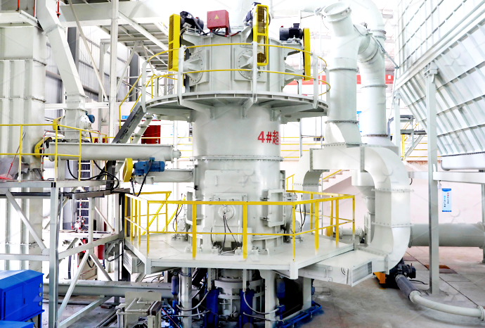
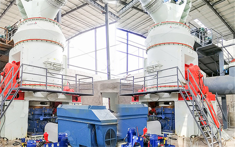
LM Vertical Roller Mill
Input size:38-65mm
Capacity: 13-70t/h
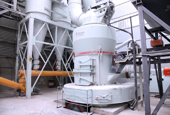
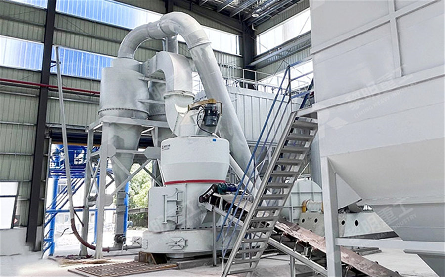
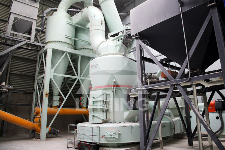
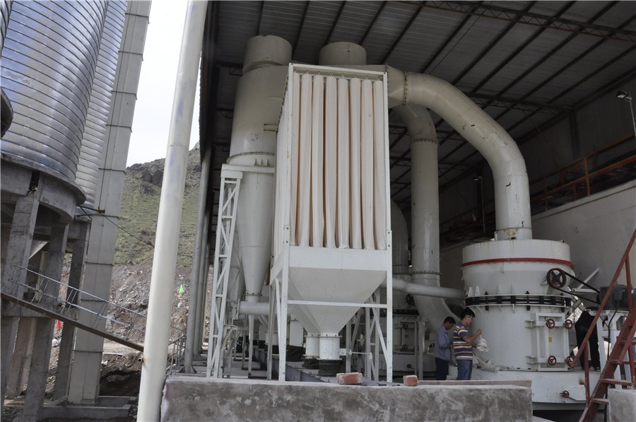
Raymond Mill
Input size:20-30mm
Capacity: 0.8-9.5t/h

Sand powder vertical mill
Input size:30-55mm
Capacity: 30-900t/h
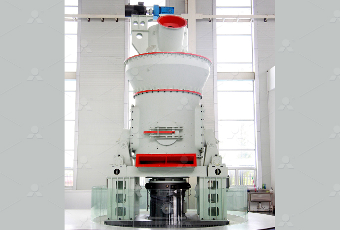
LUM series superfine vertical roller grinding mill
Input size:10-20mm
Capacity: 5-18t/h
MW Micro Powder Mill
Input size:≤20mm
Capacity: 0.5-12t/h

LM Vertical Slag Mill
Input size:38-65mm
Capacity: 7-100t/h
LM Vertical Coal Mill
Input size:≤50mm
Capacity: 5-100t/h
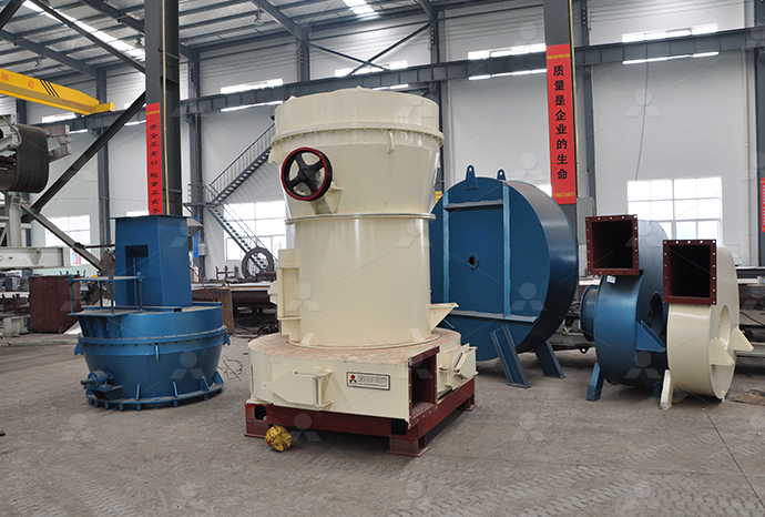
TGM Trapezium Mill
Input size:25-40mm
Capacity: 3-36t/h
MB5X Pendulum Roller Grinding Mill
Input size:25-55mm
Capacity: 4-100t/h

Straight-Through Centrifugal Mill
Input size:30-40mm
Capacity: 15-45t/h
Engineering assembly drawing

Working Drawings and Assemblies Engineering Design McGill
There are three basic types of assembly drawings: 1 An outline assembly gives a general graphic description of the exterior shape, as on this outline assembly drawing of a parallel robot Outline assemblies are used for parts catalogues (general layout of the design) and installation manuals (functionality of the mechanism), 展开Engineering drawings are defined as those drawings that communicate the requirements for the manufacture of the endproduct items, their assembly, and their installation in the end product ENGINEERING DRAWING STANDARDS MANUAL NASAWhen a machine is designed, an assembly drawing or a design layout is first drawn to clearly visualise the performance, shape and clearances of various parts comprising the machineMechanical Drawing (Assembly Drawing) Second StageEngineering drawings are the industry's means of communicating detailed and accurate information on how to fabricate, assemble, troubleshoot, repair, and operate a piece of Engineering Drawings Mechanical
.jpg)
Assembly Drawing: Importances and Types in
2024年1月10日 What is an Assembly Drawing? An assembly drawing is a technical drawing that shows how different parts and components fit together to create a larger product or structure It's like a blueprint for putting something 2023年8月1日 There are several types of assembly drawings, including exploded view drawings, detailed assembly drawings, and schematic assembly drawings Each type serves a specific purpose and provides different levels of Assembly Drawings and Their Types in Mechanical Work on this Standard considered the types of engineering drawings most frequently used by business, industry, and government communities in the United States This Standard attempts Types and Applications of Engineering Drawings NIRMTCreating assembly drawings in engineering is a multifaceted process that requires attention to detail, precision, and collaboration By following the steps outlined in this comprehensive guide, engineering professionals can produce accurate Comprehensive Guide to Creating Assembly Drawings
What Are Assembly Drawings? Different types Explained!
Among the different types of technical drawings, assembly drawings are essential for identifying each part of a machine or system in its operating position and assembly sequence Assembly drawings include a bill of materials (BOM), Remember that reading an engineering drawing can take a long time, depending on the complexity of the assembly and the experience of the reader If you're interested in learning more, our oneday introductory course will teach you How to Read An Engineering Drawing A Simple GuideCreating assembly drawings in engineering is a multifaceted process that requires attention to detail, precision, and collaboration By following the steps outlined in this comprehensive guide, engineering professionals can produce accurate Comprehensive Guide to Creating Assembly Drawings Discover the art of creating precise and comprehensive General Assembly Drawings that engineers swear by! Learn the essentials, tips, and tricks for creating flawless engineering blueprints 🛠️📐General Assembly Drawings: The Ultimate Guide to
.jpg)
ENGINEERING DRAWING STANDARDS MANUAL NASA
ENGINEERING DRAWING STANDARDS MANUAL Mechanical Engineering Branch Goddard Space Flight Center Greenbelt, Maryland August 1994 N A T I O N A L I A E R O N A U T I C S A N D S P A C E A D M I N S T R A T I O Inseparable Assembly Drawing44 47 Installation Assembly Drawing Without assembly drawings, complex engineering structures would be difficult to understand and implement It's crucial to note that assembly drawings are not static Instead, they evolve according to technological advances, reflecting the broader shifts within engineering as a fieldAssembly Drawing: Meaning, Types, Standards Vaiaengineering drawings; Construction drawings; Drawing equipment MENG 204 Mechanical Drawing Lecture Notes by: or if it is an assembly drawing, a tabulated parts list is added to the drawing The bill of materials is usually placed at the bottom right of the drawing frame, just aboveEngineering Working Drawings Basics2022年10月14日 Besides, an engineer can use an assembly drawing to represent a machine or equipment assembled from multiple parts to reach a particular function Assembly drawings are frequently used to confirm that the actual fabrication of individual parts fulfills assembly requirements Applications of Engineering DrawingEngineering Drawing Basics And Tips For Beginners LEADRP
.jpg)
Assembly Drawing: Meaning, Types, Standards StudySmarter
Without assembly drawings, complex engineering structures would be difficult to understand and implement It's crucial to note that assembly drawings are not static Instead, they evolve according to technological advances, reflecting the broader shifts within engineering as a field2023年8月7日 Top Facts About General Assembly Drawings Foundation of Engineering: GA drawings are the foundation of any engineering project, providing a clear roadmap from concept to completion Historical Roots: The use of assembly drawings dates back to the Renaissance, with Leonardo da Vinci being one of the first to create detailed blueprintsWhat Are General Assembly Drawings in Engineering? Different Engineering Drawings Mechanical Course No: M 04015 Credit: 4 PDH ABhatia Continuing Education and Development, Inc P: (877) 3225800 Figure 14 Example of an Assembly Drawing 17 Figure 15 Example of a Cutaway 18 Engineering Drawings Mechanical2024年10月14日 Engineering Part Drawing vs Engineering Assembly Drawing There are several types of engineering drawings such as weldment, electrical, hydraulic routing, etc The two most common, and the two addressed in this article are: part drawings and assembly drawings These are used for fabrication of parts and assembliesEngineering Drawings: Part Drawings vs Assembly Drawings
.jpg)
What are Assembly Drawings
2020年9月11日 Assembly Drawings are those drawings which shows an entirety of a machine or system with all its components located and identified The purpose of an assembly drawings is item identification, labeling the sequence This range includes drawings that focus on individual parts, how those parts fit together, and how the final assembly interacts with its surroundings For example, some engineering drawings are meant to convey the fine details of a single component, specifying every dimension, tolerance, and material characteristic required for its fabricationTypes of Engineering Drawings – EngineeringTechnology2024年9月4日 Types of Engineering Drawings Engineering drawings come in various types, each serving a unique purpose in the design and manufacturing process Here’s a look at some of the most common types of engineering drawings: 1 Assembly Drawings These drawings show how multiple parts fit together to form a complete unitEngineering Drawing Basics Explained [Bonus Tips Included]Engineering drawings specify the requirements of a component or assembly which can be complicated Standards provide rules for their specification and interpretation Standardization also aids internationalization , because people from different countries who speak different languages can read the same engineering drawing, and interpret it the same wayEngineering drawing Wikipedia
.jpg)
Assembly Drawings Engineering Essentials
ASSEMBLY DRAWINGS 1) Definitions 2) Components of an assembly drawing 2) Section views • Exercise: Section lines 4) Things To/Not To Include 5) Applying what we have learned • Exercise: Working drawing End Previous Engineering Graphics Essentials Independent Learning Content Enjoy the videos and music you love, upload original content, and share it all with friends, family, and the world on YouTube YouTube2024年2月24日 An engineering drawing is a visual representation that communicates the design, dimensions, and specifications of an object or assembly It serves as a critical tool for engineers, designers, and manufacturers to convey their ideas and ensure accurate productionHow to Read Engineering Drawings – learnweldingsymbolsAssembly drawing Designing Buildings Share your construction industry knowledge Assembly drawings are a type of technical drawing used to represent items that consist of more than one component They show how those components fit together and may be in the form of, orthogonal plans, sections and elevations, or threedimensional viewsAssembly drawing Designing Buildings
.jpg)
Mechanical Drawing (Assembly Drawing) Second Stage
1233 Sub Assembly Drawing Many assemblies such as an automobile, lathe, etc, are assembled with many preassembled components as well as individual parts These preassembled units are known as subassemblies A subassembly drawing is an assembly drawing of a group of related parts, that form a part in a more complicated machineMechanical Engineering Drawings are a critical part of the design process, and any engineering will be expected to understand them They are used to represent how a part or assembly is designed and how it will be manufactured This Mechanical Engineering Drawing and Design 3Q 2023年5月21日 IndustrySpecific Standards: Certain industries have specific standards tailored to their unique requirementsFor example, the automotive industry follows standards such as ISO 10209 for vehicle assembly drawings Similarly, the aerospace industry adheres to standards like ASME Y14100 for engineering drawing practicesIntroduction to Engineering Drawings The Questions and 2021年12月16日 The document’s title in an engineering drawing block is found in the bottom righthand corner of the page Also known as the information blocks, it includes the part name, the names of the people who worked on the part Engineering Drawing Overview Basic
Assembly Drawing Overview Research Examples Perlego
340 CHAPTER 10 Assembly Drawing s Figure 10‐1 Assembly Drawing Figure 10‐2 Sub Assembly Drawing Assembly Drawing s Explored 341 Figure 10‐3 Exploded Assembly View Figure 10‐4 Two Orthographic Views 342 CHAPTER 10 Assembly Drawing s Figure 10‐5 Assembly with Sectioned View not sectioned or “in the round” These parts include screws, Typical assembly drawings include gearbox drawings, roller drawings, guard system drawings The assembly drawing will generally include at least three orthographic views with sections as needed to clearly show all of the details and their relative positionsMechanical Engineering Drawings Roy Mech2024年2月19日 Master mechanical engineering drawings: interpret schematics, blueprints, title blocks, projections, sections, dimensions, and assembly tips Introduction to Mechanical Engineering Drawings Engineering drawings, also known as mechanical drawings or blueprints, are technical, twodimensional drawings that visually communicate the requirements for Understanding Mechanical Engineering Drawings: A Simple 2024年9月24日 Discussion of assembly drawings can get a little heated from time to time The driving concept behind what makes assembly drawings effective or not remains the same It's mostly a matter of perspective as to whether they are prioritized enough by decisionmakers or not This type of drawing has been overlooked by decisionmakers on enoughHow to Design Effective Assembly Drawings for Consumer Products
ENGINEERING DRAWING N3 Future Managers
ENGINEERING DRAWING N3 () 25 July 2019 (XPaper) 09:00–13:00 REQUIREMENTS: ONE A2 drawing sheet : This question paper consists of 10 pages and 1 answer sheet QUESTION 3: ASSEMBLY DRAWING [30] Correctness 18 Line work 5 Accuracy 5 Layout and neatness 2 QUESTION 4 MRCET(UGC AUTONOMOUS) Dept of Mechanical Engineering Page 6 ENGINEERING DRAWING PRACTICE MANUAL I BTech LETTERING Lettering is defined as writing of titles, subtitles, dimensions, etc, on a drawing Importance of Lettering: To undertake production work of an engineering component as per the drawing, the size and otherENGINEERING DRAWING PRACTICE MANUALOur experienced engineering detailing team ensures that, the assembly drawings we produce depict precise information for the site workers to assemble the components seamlessly Our 3D modeling services for an assembled Precise Assembly Drawings Advenser Engineering Any engineering drawing should show everything: a complete understanding of the object should be possible from the drawing If the isometric drawing can show all details “Assembly” Drawings An isometric view of an “assembled” pillowblock bearing system is shown in figure 13Design Handbook: Engineering Drawing and Sketching
Types and Applications of Engineering Drawings ASME
ASME Y1424, “DRAWINGS TYPES AND APPLICATIONS OF ENGINEERING DRAWINGS”, was adopted on 14 February 2000 for use by the Department of Defense (DoD) 61 Assembly Drawing 26 62 Detail Assembly Drawing Any engineering drawing should show everything: "Assembly" Drawings An isometric view of an "assembled" pillowblock bearing system is shown in figure 13 It corresponds closely to what you actually see when viewing the object from a particular angleEngineering Drawings University of CambridgeCreate an assembly drawing in Inventor Create an assembly drawing with an exploded view and parts listCreate an assembly drawing in Inventor Autodesk2024年9月14日 Check the title block for basic information about the drawing The title block appears either at the top or bottom of an engineering drawing Read this first to find out crucial information about the drawing, including: The name and contact information for the company producing or distributing the part4 Ways to Read Engineering Drawings wikiHow
Drawing Format and Elements Engineering Design McGill
First, we will consider the sheet sizes, drawing format, title blocks, and other parameters of the drawing form Standard Sheet Sizes In Table 1 are shown the most widely used A and B Series of the ISO drawing sheet sizes, with A4 being the most popular size The terms used in the table are clarified here: The Inside border encloses the working area, including the title block and other 4 Section Views Section views are used extensively to show features of an object or an assembly that are not easily visible from the exterior This method can be used with both simple and complex objects and involves the use of a cutting plane that dictates what portion of the object you want to remove to reveal a more complex interiorSection Views – Engineering Graphics and DesignEngineering Drawing American Society of Mechanical Engineers standard ASME Y1435M was issued in 1997 to describe the ASMEapproved format for tracking revisions and other changes to engineering drawingsASME Standards for the Revision of Engineering Drawings