


MTW European Type Trapezium Mill
Input size:30-50mm
Capacity: 3-50t/h
LM Vertical Roller Mill
Input size:38-65mm
Capacity: 13-70t/h
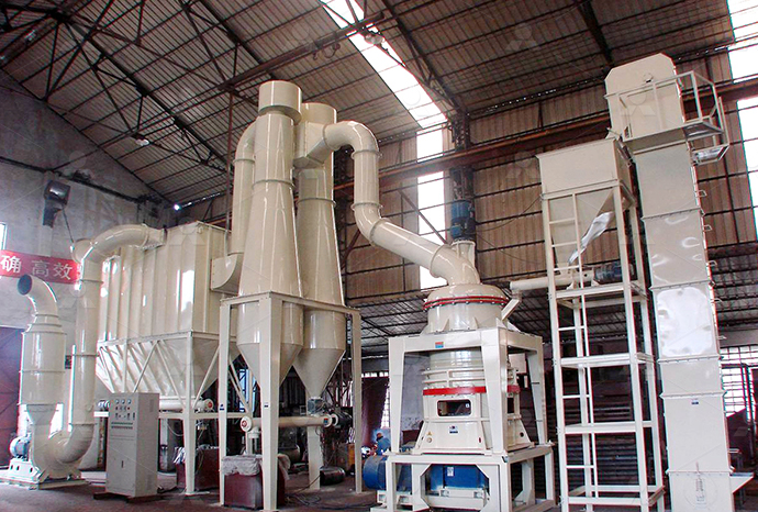
Raymond Mill
Input size:20-30mm
Capacity: 0.8-9.5t/h
Sand powder vertical mill
Input size:30-55mm
Capacity: 30-900t/h
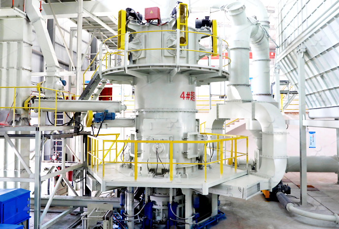
LUM series superfine vertical roller grinding mill
Input size:10-20mm
Capacity: 5-18t/h
MW Micro Powder Mill
Input size:≤20mm
Capacity: 0.5-12t/h

LM Vertical Slag Mill
Input size:38-65mm
Capacity: 7-100t/h
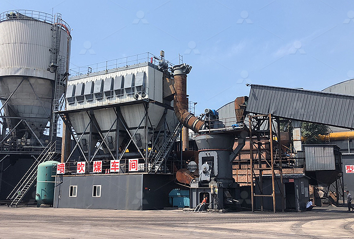
LM Vertical Coal Mill
Input size:≤50mm
Capacity: 5-100t/h
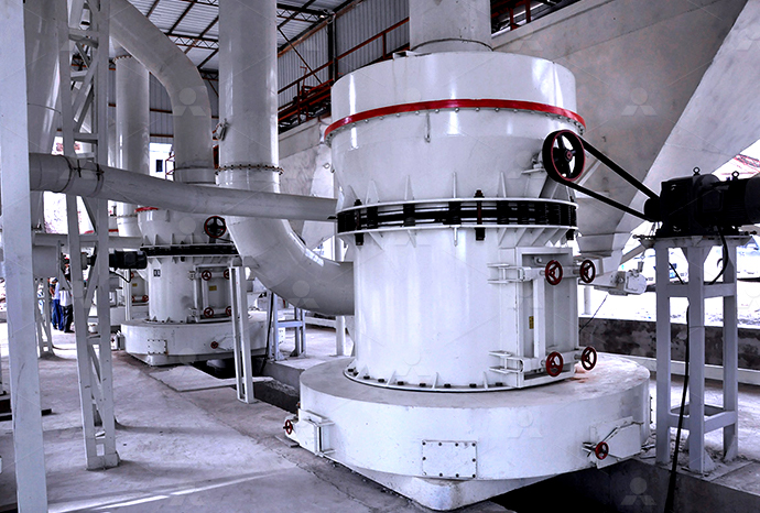
TGM Trapezium Mill
Input size:25-40mm
Capacity: 3-36t/h
MB5X Pendulum Roller Grinding Mill
Input size:25-55mm
Capacity: 4-100t/h

Straight-Through Centrifugal Mill
Input size:30-40mm
Capacity: 15-45t/h
Cylinder CAD process flow chart
.jpg)
Manufacturing flowchart for the case study cylinder
A thickwalled, cylindrical preform is flowformed using a single operation into a thinwalled barrel with integral longitudinal stiffenersFind the technical support for CAD Drawings, STP and PDF updates you need for your Emerson products and systems Use your Coriolis sensor and transmitter model code to access 2D and Drawings Center Emerson USLearn how to size and draw a cylinder with Parker’s 2D/3D Cylinder Configurator It allows anyone to design a hydraulic or pneumatic cylinders, create a model codes and download CAD Parker 2D/3D Cylinder Configurator Parker Hannifin Corporation2018年1月1日 Engineers and designers may notice an increased productivity in their work using the API (Application Programming Interface) of a general purpose CAD system Using this Pneumatic cylinder design using cadbased programming
PNEUMATIC CYLINDER DESIGN USING CADBASED
Figure 1 Flow chart of Cylin3DerCADbased application 32 Cylin3Der flowchart During the first stage of the design process, the application performs a number of calculations inThe Process Flow Diagram •Shows the flow of process and the equipment involved in the process •Shows the relationships between the major components minus the details • Are Process Flow / Instrumentation Drawings PFD / PID PNWS To adapt the requirements of the mass productmade production model, the threedimension parametric design software about hydraulic cylinder CAD is developed This software HYDRAULIC CYLINDER CAD DESIGN SYSTEM BASED ON In AutoCAD MEP, a process flow diagram is also called a schematic diagram You create process flow diagrams by using the schematic symbols and lines that model the components of a Working with Process Flow Diagrams Digital River

LPG Cylinder Manufacturing Process Flow Chart With Raw Material
This document describes the manufacturing process and materials used to produce regular and premium 125 kg LPG cylinders at Sundarban Industrial Complex Ltd in Mongla, Bagerhat 2023年1月5日 The operation process chart flow process chart is basically a tool for method studyTo implement the lean manufacturing concept its tools like kaizen, 6 ‘S’, SMED, OEE, VSM, and pokayoke the basic requirement is Operation Process Chart (OPC) And Flow Process Unlock the flow diagrams language with our flowchart symbols guide 🔸 Everything you need to know about basics of flowchart, from ️ decision points to ️ process steps, explore the meaning behind each symbol and master the art of creating Basic of Flowchart: Meaning and Symbols ConceptDraw2024年8月18日 This symbol represents a complex process or operation already explained elsewhere in the flowchart It's a rectangle with a line at each end of the shape It helps depict subprocesses, or the smaller processes within a larger Learn About 28 Flowchart Symbols and Their
.jpg)
Flowchart symbols meanings: A guide with examples Slickplan
As you get into creating more complex flow charts user flow, data processing, process flow, etc you'll need a bigger library of flowcharting symbols Behold the advanced flowchart key Flow line connectors Just as the flowchart symbols have universally understood meanings, so 2016年6月10日 WHAT ARE PID SYMBOLS? DEFINITION OF PID SYMBOLS PID symbols refer to the standard notations and graphical representations used on Piping and Instrumentation Diagrams (PIDs) to depict the components and systems involved in process flows within a facility These symbols are essential for engineers, operators, and workers to Free PID Symbols for Piping, Valves, Equipment • ProjectmaterialsThis document describes the manufacturing process and materials used to produce regular and premium 125 kg LPG cylinders at Sundarban Industrial Complex Ltd in Mongla, Bagerhat For regular cylinders, the process involves blanking, cutting, forming, welding, heat treatment, testing, and painting of cylinder bodies and handles made from HR coil and welding wire For premium LPG Cylinder Manufacturing Process Flow Chart With Raw Getting Started Learn how to make any type of visual with SmartDraw Familiarize yourself with the UI, choosing templates, managing documents, and more Templates get inspired by browsing examples and templates available in SmartDraw Diagrams Learn about all the types of diagrams you can create with SmartDraw Flowchart Process Flow Charts, Templates, How To, and More
Basic Flowchart Symbols and Meaning Mechanical Drawing
Flowchart Symbols and Meaning Provides a visual representation of basic flowchart symbols and their proposed use in professional workflow diagram, standard process flow diagram and communicating the structure of a welldeveloped web site, as well as their correlation in developing online instructional projects See flowchart's symbols by specifics of process flow 2010年7月21日 The flowchart displays the process for calculating the volume and surface area of a cylinder It starts by inputting the radius and height, then uses formulas to calculate the volume as 314*radius*radius*height and the surface area as 2*314*radius*radius + 2*314*radius*height, and ends by outputting the volume and surface area Read lessFlowchart for volume and surface area of cylinder PDF SlideShareDownload scientific diagram Manufacturing flowchart for the case study cylinder fabricated through the conventional metallic manufacturing process from publication: CostBenefit Analysis for Manufacturing flowchart for the case study cylinder fabricated 5 Display ‘the volume of the cylinder is” and volume 6 End Flowchart end Read radius and length Volume = area*length Area =radiusradiusꙥ Display volume of cylinder start Write a pseudocode that converts pounds into kilograms Exercise 2 pseudocode and a flowchart LAB
.jpg)
LPG CYLINDER PRODUCTION LINES REPKON
PROCESS STEPS LPG Cylinder Production is composed of several sheet metal forming, surface treatment and testing processes The process starts with blanking, deep drawing and piercing, trimming and joggling Next are the welding operations for valve boss, valve guard ring, foot ring and the two halves The finished cylinder is thenprocess is supported by a group of tools incorporated These tools deal with: the creation of the components (solid models) of the cylinder, the assembly of the finished product, rendering andPNEUMATIC CYLINDER DESIGN USING CADBASED Flowchart symbols can show the flow and logic between ideas and concepts Some symbols are used in writing, some in print, and some in advertising Flowcharts can be used in the following contexts: to depict the process a company follows to create its products, to provide information about the history of a company, to explain the organizational structure, and to outline the main Flowchart Symbols with Meanings Complete Tutorial EdrawMax2023年9月19日 These cylinders are widely used for household cooking, heating, and various industrial applications In this detailed guide, we will walk through the key stages of the LPG cylinder manufacturing process 1 Material Procurement: The first step in manufacturing LPG cylinders is the procurement of highquality raw materials, primarily steel sheetsA Detailed Guide to LPG Cylinder Manufacturing Process
181 Process Flow Diagram (PFD) Symbols for Engineers
181 Process Flow Diagram (PFD) Symbols for Engineers Welcome to our process flow diagram symbols list Scroll down and use the table of contents on the left to navigate this page and see the different symbol types most commonly used by engineersBut first, let’s review the purpose and benefits ofFlowcharts Basic Syntax Flowcharts are composed of nodes (geometric shapes) and edges (arrows or lines) The Mermaid code defines how nodes and edges are made and accommodates different arrow types, multidirectional arrows, and any linking to and from subgraphsFlowcharts Syntax Mermaid 2022年12月28日 Difference between Algorithm and Flowchart If you compare a flowchart to a movie, then an algorithm is the story of that movie In other words, an algorithm is the core of a flowchartActually, in the field of computer programming, there are many differences between algorithm and flowchart regarding various aspects, such as the accuracy, the way they display, Explain Algorithm and Flowchart with Examples Edraw2024年5月17日 Decision: This symbol represents a decision you or your team need to make to get to the next step of the processTypically, it’s a true or false decision or a yes or no question that you need to answer Stored data: This symbolizes a data file or database “Or” symbol: This indicates that the process flow continues in three or more branchesFlowchart 101: Symbols, types, and how to create them
LPG Cylinder Production Process Flow ROK Teknik
Welding operation of LPG Cylinder makes the welded parts chemically change their situation and harden the welded areas To relieve stress of the cylinder heat treatment is applied We use furnace method to equally distribute the heat on the cylinder 6 Hydro Static Testing of 2024年7月30日 With a process flowchart, you can successfully plan a project Unlike the other type of flowcharts, the process flowchart can apply to anything It uses standard languages like business process modelling and notations This flow diagram can help you visualise the processes within an organisation The other functions of a process flowchart include:A guide to flowchart symbols (meaning, types and examples)2023年12月7日 Additionally, it helps you compile all the data you need firsthand to draw the process on the flowcharting tool #4 Reviewing the Process Flow It enables you, the team, and business stakeholders to collaboratively review all The Most Common Flowchart Symbols ExplainedThe following is a basic overview, with descriptions and meanings, of the most common flowchart symbols also commonly called flowchart shapes, flow diagram symbols or process mapping symbols, depending upon what type of Flowchart Symbols Defined: Business Process Map
What is a flowchart? Examples, tips, and templates Mural
2024年8月7日 Terminator, Start/End: Every process has a start and an end point Use the oval shape to identify both moments Action, process: The rectangle shape is used for actions or instructions, the things that must be done Decision: The diamond shape indicates a step in the process that asks a question or requires a decisionDownload scientific diagram Process Flow Chart of Sand Casting [6] from publication: Quality Improvement for Dimensional Variations in sand Casting Using Quality Control Tools Abstract Process Flow Chart of Sand Casting [6] ResearchGateenterprises, developing the CAD software that possesses PDM feature for the product series design possesses the important real significance 2 GENERAL SCHEME OF HYDRAULIC CYLINDER CAD SYSTEM Hydraulic cylinder is the most usual component of executing in hydraulic system It is widely applied in common machinery, engineering machinery,HYDRAULIC CYLINDER CAD DESIGN SYSTEM BASED ON 2023年6月20日 Once all the processes in the IC fabrication process flowchart are completed, the IC is ready for packaging and postfabrication testing and analysis Cadence software offers tools to handle the entire IC fabrication process flow IC Fabrication Process Flow Chart Cadence
Flowchart Maker Online Diagram Software
Flowchart Maker and Online Diagram Software drawio is free online diagram software You can use it as a flowchart maker, network diagram software, to create UML online, as an ER diagram tool, to design database schema, to build BPMN online, as a circuit diagram maker, and more drawio can import vsdx, Gliffy™ and Lucidchart™ files 6 Sheet Stock Sizes and Gauge Lookup Chart 7 Stock Material Thickness Tolerances 8 Quoting Formats: 3D CAD and DXF Files 9 DXF Requirements 10 General Design Tips 11 Wall Thickness 12 Holes and Slots 13 Bends 14 Curls and Countersinks 15 Hems 16 Relief Cuts and Corner Fillets 17 Notches and Tabs 18 Finishes Postprocesses for Sheet MetalSheet Metal Fabrication Design GuideMicroBulk systems are available for oxygen, nitrogen, argon, carbon dioxide, nitrous oxide (N2O), LNG in high pressure, high flow applications including laser cutting, metal processing fabrication, precision welding, laboratory research, medical oxygen, food beverage packaging/preservation, electronics manufacture testing, inert purging blanketingMicroBulk Storage Systems Chart IndustriesProcess Flow Cad Free download as PDF File (pdf), Text File (txt) or read online for free CSC eGovernance Services India Limited has partnered with SIEMENS Industry Software (India) Pvt Ltd to offer online Computer Aided Process Flow Cad PDF Computer Aided Design
Seven Most Used And Important Flowchart Symbols
The circleshaped symbol is typically small and is used as a Connector to show a jump from one point in the process flow to another They’re also known as the connector symbols Connectors are usually labeled with capital letters (A, B, PROCESS: Iterate to the next character in password PROCESS: Increment passlength DECISION: Is the current character a number? FLOWLINE: If not, go straight back to step 4 and continue to iterate over the entire password PROCESS/FLOWLINE: If so, set the containsnumber variable to True and then go back to step 4Pseudocode and Flowcharts CodecademyCAD, Computer aided design, garments pattern made in computer using different CAD software CAD is the 1st step of Garments manufacturing, garments measurement ,shape and pattern can be controlled easily Here I a am giving CAD room working procedure from from starting pattern making to bulk marker printing flow chart wise, your concept will be clear about CAD work CAD/Pattern Room SOP, Procedure and working Flow chart in Create a process flow diagram online Break down complex processes into smaller steps with efficient process flows Create a process flow diagram on Canva Whiteboards and use it to visualize the big picture and your role within it With a host of creative elements and design tools, you have everything you need to take control of your workflowFree Process Flow Diagram Maker and Examples Canva
.jpg)
Flowchart Symbols SmartDraw
There are two different types of approaches to symbols in data flow diagrams: Yourdon and Coad and Gane and Sarson In the Yourdon and Coad way, processes are depicted as circles, while in the Gane and Sarson diagram the processes are squares with rounded corners Learn more about data flow diagramsDownload scientific diagram Process flowchart of aluminium extrusion a Conventional b Direct recycling from publication: A review on direct hot extrusion technique in recycling of aluminium Process flowchart of aluminium extrusion a Conventional b the cylinder and swirl is generated within the inlet port shown in Figure 10 And illustration of formation process of swirl flow in the cylinder shown in Figure 11 and formation process of tumble flow during the induction process is shown in figure 12 3 Prototype Development and Validation With reference to Figure 10Cylinder Head Intake Port Design InCylinder Airflow Patterns Our botton ring process flow: Raw material→ Punch slot, holes→Rolling circle→Botton ring welding→ Botton dish ends Step 4 The process of cylinder guard In the production process of LPG cylinders the welding seam is an important part of connecting the top and bottom shellA detailed guide to lpg cylinder manufacturing process
The flow diagram of ComputerAided Design and Manufacturing (CAD
The world is a growing place with great technological advancement in all areas of life For some decades now, various disciplines and industries have been engaged in using ComputerAided Design