


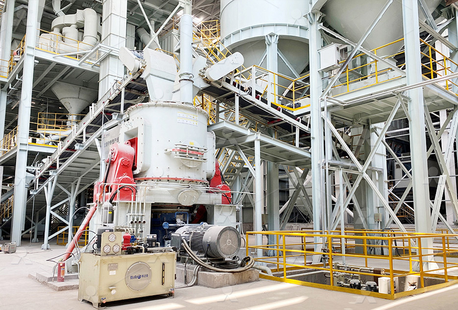
MTW European Type Trapezium Mill
Input size:30-50mm
Capacity: 3-50t/h
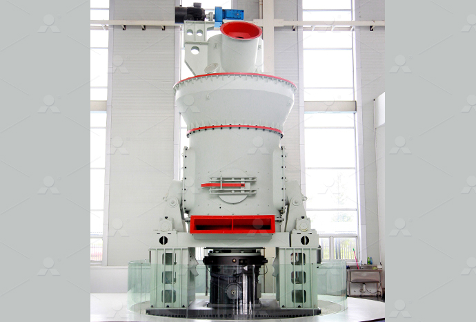
LM Vertical Roller Mill
Input size:38-65mm
Capacity: 13-70t/h
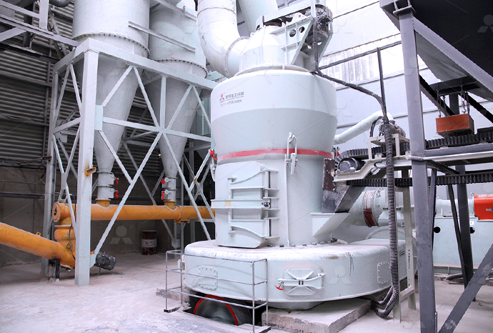
Raymond Mill
Input size:20-30mm
Capacity: 0.8-9.5t/h
Sand powder vertical mill
Input size:30-55mm
Capacity: 30-900t/h
LUM series superfine vertical roller grinding mill
Input size:10-20mm
Capacity: 5-18t/h
MW Micro Powder Mill
Input size:≤20mm
Capacity: 0.5-12t/h

LM Vertical Slag Mill
Input size:38-65mm
Capacity: 7-100t/h
LM Vertical Coal Mill
Input size:≤50mm
Capacity: 5-100t/h
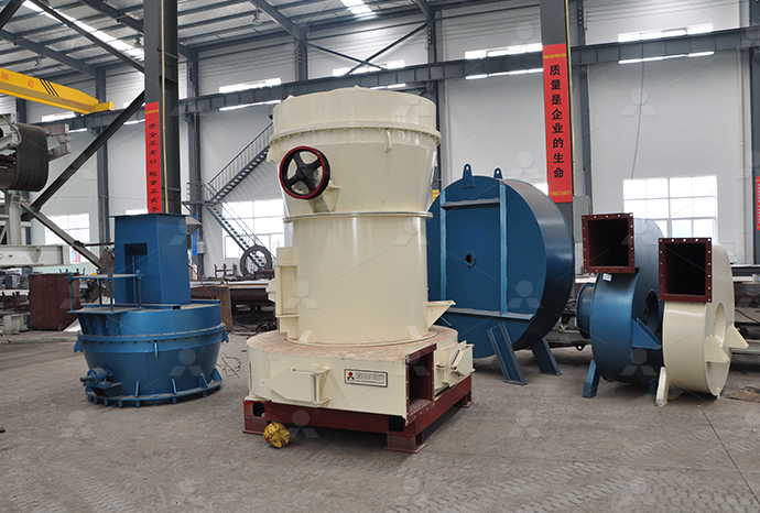
TGM Trapezium Mill
Input size:25-40mm
Capacity: 3-36t/h
MB5X Pendulum Roller Grinding Mill
Input size:25-55mm
Capacity: 4-100t/h

Straight-Through Centrifugal Mill
Input size:30-40mm
Capacity: 15-45t/h
Schematic diagram of gear shaping mechanism
.jpg)
Schematic illustration of cutting profile and area
Gear shaping is a widely applied technology to produce spur gears Generally, the pinion cutter and the gear workpiece rotate uniformly with a given gear ratio during the conventional gearPrinciple of Operation of the Shaping Machine 1 Shaper machine is used for generating flat surfaces 2 Single Point Tool reciprocates on the job 3 Job is fed across the tool 4 Tool is Shaping Machine its Operations University of Technology, IraqRing gear is an important part of high power transmission system Because of its thin wall and low stiffness, it is easy to cause deformation in the process of gear shaping, which affects itsSchematic diagram of gear ring gear shapingGear shaping is a widely applied technology to produce spur gears Generally, the pinion cutter and the gear workpiece rotate uniformly with a given gear ratio during the conventional gearFlowchart and schematic illustration of the algorithm of
.jpg)
Shaper Machine – Types, Parts, Working, Operations,
Shaper Machine Mechanism : In a shaper rotary movement of the drive is converted into reciprocating movement by the mechanism contained within the column or frame of the machine The ram holding the tool gets the 2015年1月1日 Based on a morphological approach, individual kinematic shaping schemes are classified, and their mathematical models are developed The shaping schemes, as well as the Design of Shaping Machine and Tooling Systems for Gear Gear shaping operation is a type of continuous indexing method of gear machining The kinematics of the machining process of a work gear with the gear shaper cutter is illustrated in Gear shaping – Knowledge and References – Taylor FrancisThree important parameters are to be controlled in the process of gear hobbing indexing movement, feed rate and angle between the axis of gear blank and gear hobbing tool (gear Gear Hobbing – Marples Gears

Design and optimization of complex mechanism flip
2023年2月2日 In this paper, the cam connecting rod system of the highspeed group vertical machine flipping shaping mechanism is the research object In order to solve the key problem that the flipping shaping mechanism cannot Fig 4 shows the schematic diagram of flipshaping mechanism and establishes a coordinate system The overturning mechanism is mainly composed of a cam pendulum mechanism, Fig 4 The schematic diagram of flipping mechanismWell, in this reading, we’ll explore what a shaping machine is, its parts, diagram, types, classifications, and how Geared Type Shaping Machine The rack and pinion mechanism is responsible for generating the reciprocating The bull What is Shaping Machine? – Its Diagram and How it 18 CHAPTER 2 THE MECHANISM OF SPEECH PRODUCTION Figure 21: Schematic diagram of the human vocal mechanism The nasal tract constitutes an ancillary path for sound transmission It begins at the velum and terminates at the nostrils In the adult male the cavity has a length of about 12 cm and a volume onThe Mechanism of Speech Production University of Illinois

Hydraulic shaper machine – Working, Circuits, Advantages,
To generate reciprocating motion of ram of shaping machine we having two alternatives: By using a fourbar mechanism ( Cylinder, Piston, connecting rod, and crank ) driven by the motor This machine is called a mechanical shaping machine By using a hydraulic DA cylinder This machine is called a hydraulic shaping machineDownload scientific diagram Schematic of the magnetic gear from publication: Comparative Study Between Mechanical and Magnetic Planetary Gears The paper deals with the possibility of Schematic of the magnetic gear Download Scientific DiagramThe gearshapingbased electric vehicle transmission showcased favorable economic and technical performance, while its excitation response mechanism provided valuable guidance for mass productionSchematic diagram of magnetic gear based WPTexternal gear mesh may share identical structural topology Figure 3(a) is the functional schematic of a spur gear set with an external gear mesh, whereas Figure 3(b) is the functional schematic o f another spur gear set with an internal gear mesh Each of these two gear sets has three links Gear 2 meshes with gear 3, and link 1 is the carrierA Study of Structural Representation of Mechanisms Kinematic
.jpg)
Gear Hobbing – Marples Gears
The schematic diagram of the set up of a gear hobbing machine can be seen in the figure “Prediction and optimization of hobbing gear geometric deviations” Mechanism and Machine Theory (2018): 288301 Web Endoy, R (1990) Gear hobbing, shaping, and shaving: A guide to cycle time estimating and process planning Download scientific diagram Schematic of doublehelical gear with Timoshenko beam elements from publication: Dynamic modeling of doublehelical gear with Timoshenko beam theory and experiment Schematic of doublehelical gear with Timoshenko beam elementsBasic Gear Mechanisms: Cars, clocks, and can openers, along with many other devices, use gears in their mechanisms to transmit power through rotation Gears are a type of circular mechanical device with teeth that mesh to transmit Basic Gear Mechanisms : 21 Steps (with Pictures)Shaping Machine its Operations 1 Principle of Operation of the Shaping Machine 2 Types of shaper 3 Construction of the Shaper 4 Mechanisms in a Shaper 5 Shaper operations 6 How to specify a Shaper? 7 Introduction to Planer N = Rotational speed of bull gear (rpm) R s = Stroke ratio Cutting time = width / [N * feed] ME 113, By A B Shaping Machine its Operations University of Technology, Iraq
.jpg)
The gear system (a) and schematic diagrams of different
Download scientific diagram The gear system (a) and schematic diagrams of different clearance configurations (b, c) from publication: Effect of clearance configuration on gear system dynamics valid by using gear shaping experiments and toothflank detections 2 Gear shaping strategy for internal helical noncircular gears As shown in Fig 1, the pitch circle of shaper cutter, revolving as wb, and the pitch curve of gear billet, revolving as wc, are in continuous pure rolling contract in the same directionResearch on gear shaping strategy for internal helical noncircular 2023年7月18日 Considering the gear meshing principle, a coordinate system for shaping internal splines is established, as illustrated in Fig 1, where S t0 represents the fixed coordinate system of the gear shaping tool and z t0 coincides with the rotational axis of the gear shaping tool S g0 represents the fixed coordinate system of the internal spline, and the z g0 axis coincides with Study of the surface generation mechanism and roughnessDownload scientific diagram Schematic diagram of the 3D landing gear mechanism from publication: Kinematic Singularity and Bifurcation Analysis of Sidestay Landing Gear Locking Mechanisms A Schematic diagram of the 3D landing gear mechanism
.jpg)
LABORATORY MANUAL KINEMATICS OF MACHINE ME212F
gear shaping process Note: 1 At least Ten experiments are to be performed in the Semester 2 Diagrams of 4 Bar Mechanisms, Single Double slider crank mechanisms 4 Working Construction of 4 Bar Mechanisms, Single Double slider crank mechanisms 5Download scientific diagram Schematic diagram of helical gear system from publication: Optimization of bias modification and dynamic behavior analysis of helical gear system A generalized Schematic diagram of helical gear system ResearchGateDownload scientific diagram Schematic diagram of the gear test rig from publication: Spalling formation mechanism for gears Though the basic phenomenon of wear on gear tooth contact surfaces Schematic diagram of the gear test rig ResearchGateDownload scientific diagram Schematic of an automotive differential from publication: DESIGN OF A SPHERICAL CAM MECHANISM FOR AN AUTOMOTIVE DIFFERENTIAL Spherical camfollower mechanisms are Schematic of an automotive differential Download Scientific Diagram
Basics of Speed Governing Mechanisms and Modelling RCET
Basics of Speed Governing Mechanisms and Modelling The speed governor is the main primary tool for the LFC, whether the machine Fig1 Schematic diagram of speed governing mechanism Δx A = K c ΔP C (1) The link point ‘C’ will move upward because of Download scientific diagram Block diagram of the steering gear system from publication: A Backstepping Approach to Ship Course Control A Backstepping Approach to Ship Course Control As an Block diagram of the steering gear systemFigure \(\PageIndex{5}\): The diagram shows a simple gear system with gears A and B interacting As a constraint, we can assume that the speed of the teeth at the point of contact will be the same If this were not true, the teeth of one 112: Belt and GearDriven Systems Engineering This gear is connected to the input shaft of the transmission and receives power from the engine The sun gear is surrounded by multiple planetary gears, which are mounted on a carrier The ring gear, which is larger in diameter than the sun gear, is also part of the planetary gear set and surrounds the planetary gears and carrierUnderstanding the Automatic Transmission Components Diagram

Understanding Planetary Gear Systems: Detailed Schematic Analysis
2023年12月22日 Understanding the Intricacies of Planetary Gear Schematic Dive deep into the fascinating world of gear mechanics, with our focus on planetary gear schematic The essence of this mechanism lies in its layout, which resembles a solar system, with a central sun gear encircled by planet gearsDownload scientific diagram Schematic Diagram of Bevel Gear Transmission from publication: Singularityfree algorithms and design scheme for a new 6DOF parallel haptic device It is known that Schematic Diagram of Bevel Gear Transmission2023年11月3日 A shaper machine is working on the following principle A shaper machine holds the Single point cutting tool in ram and the workpiece is fixed over the table; The ram holding the tool reciprocates over the workpiece and metal is cut during the forward stroke called a cutting stroke; No metal is cut during its return stroke is called an Idle strokeShaper Machine: Working, Parts, Types, and Operations (With PDF)Download scientific diagram Schematic diagram of grinding mechanism from publication: Prediction and experimental study on thermal stress in multitooth form grinding of cycloid gear Cycloid Schematic diagram of grinding mechanism ResearchGate

Schematic diagram of the wear mechanism ResearchGate
Download scientific diagram Schematic diagram of the wear mechanism from publication: Effect of matrix hardness on the impact abrasive wear Performance of ZTAp/steel architecture composite Download scientific diagram Schematics of the worm gear drive (after [17]) from publication: A passiveassist design approach for improved reliability and efficiency of robot arms The purpose Schematics of the worm gear drive (after [17]) ResearchGateDownload scientific diagram Schematic drawing of worm gear shaft section from publication: Meshing theory of axial arc tooth profile cylindrical worm drive In this paper, the axial arc tooth Schematic drawing of worm gear shaft sectionDownload scientific diagram The schematic of planetary gear system from publication: Motion Periods of Planet Gear Fault Meshing Behavior Vibration sensors are, generally, fixed on the The schematic of planetary gear system Download Scientific Diagram
Schematic of the DC motor and gearbox Download
Download scientific diagram Schematic of the DC motor and gearbox from publication: On the dynamic behaviour of a fourbar linkage driven by a velocity controlled DC motor The dynamic Download scientific diagram Structures and schematic diagram of the selflocking mechanism ((a) physical structure, (b) planet gear reduction, (c) selflocking mechanism) from publication Structures and schematic diagram of the selflocking mechanism Download scientific diagram The schematic diagram of gear contact from publication: Investigation of Contact Performance of CaseHardened Gears Under Plastoelastohydrodynamic Lubrication Case The schematic diagram of gear contact ResearchGateDriving Mechanism Different types of driving mechanisms are used in different types of presses like a cylinder and piston arrangement in a hydraulic press, crankshaft and eccentric mechanisms in a mechanical press, etc these mechanisms are used to drive ram by transferring power from the motor to ram Controlling MechanismsPress Machine – Types , Parts , Diagram , Specifications
.jpg)
Schematic diagram of the wear mechanism ResearchGate
Download scientific diagram Schematic diagram of the wear mechanism from publication: Effects of the surface processing on the tribological performance of C/SiCs under dry friction A new PDF On Dec 3, 2020, Maile Zhou and others published Method for generating noncircular gear with addendum modification and its application in transplanting mechanism Find, read and cite all (PDF) Method for generating noncircular gear with addendum Download scientific diagram Schematic illustration of cutting profile and area distribution of conventional gear shaping from publication: An efficient spur gear shaping method based on Schematic illustration of cutting profile and area distribution of Download scientific diagram Schematics diagram of abrasive wear mechanism from publication: Tribology and Development of Wear Theory: Review and Discussion In this review, the classical and Schematics diagram of abrasive wear mechanism