


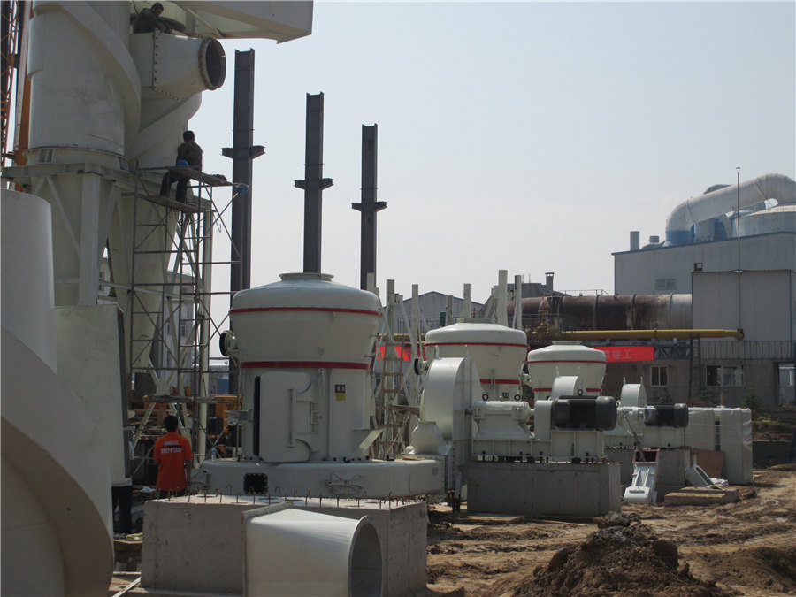
MTW European Type Trapezium Mill
Input size:30-50mm
Capacity: 3-50t/h
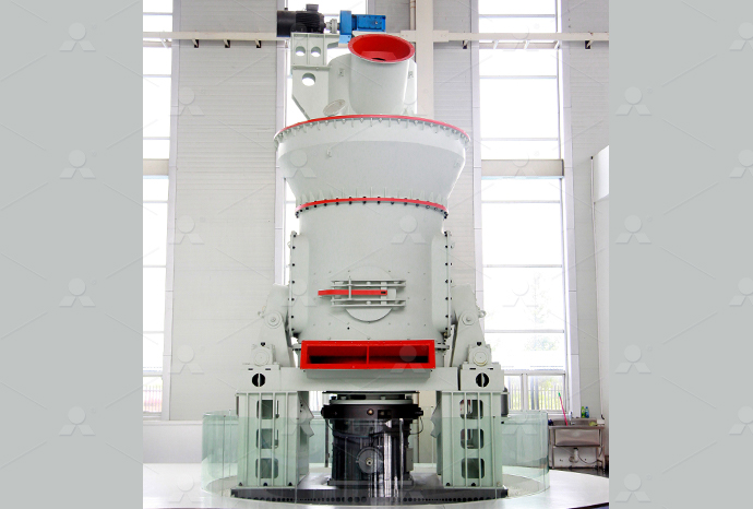
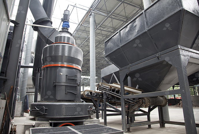
LM Vertical Roller Mill
Input size:38-65mm
Capacity: 13-70t/h
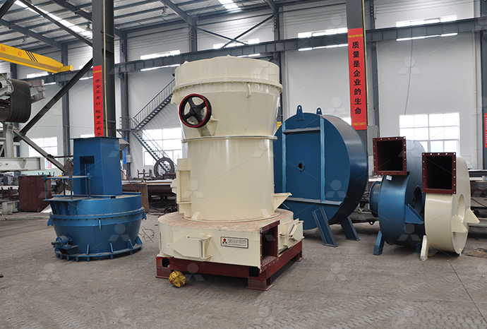
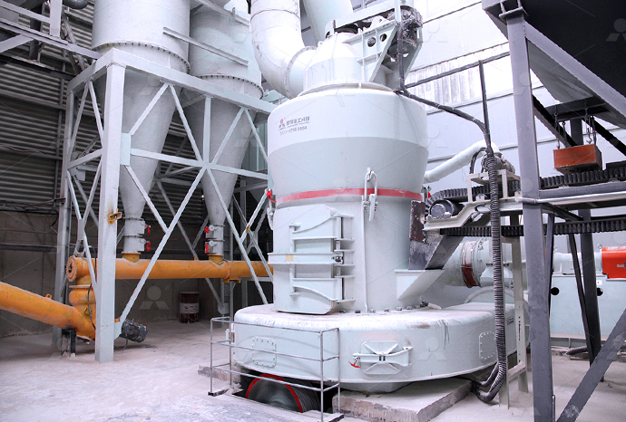
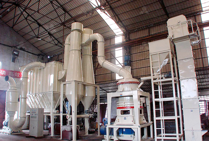
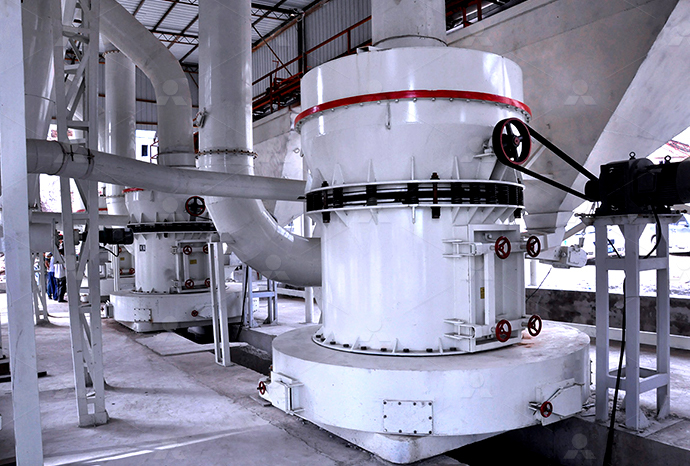
Raymond Mill
Input size:20-30mm
Capacity: 0.8-9.5t/h

Sand powder vertical mill
Input size:30-55mm
Capacity: 30-900t/h

LUM series superfine vertical roller grinding mill
Input size:10-20mm
Capacity: 5-18t/h
MW Micro Powder Mill
Input size:≤20mm
Capacity: 0.5-12t/h

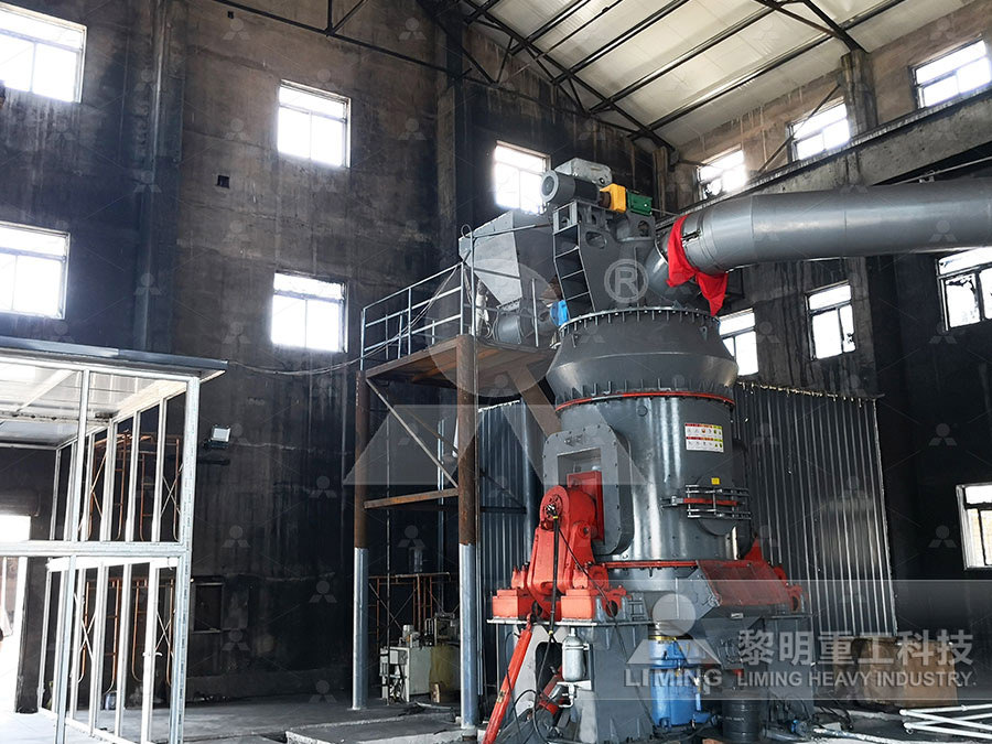
LM Vertical Slag Mill
Input size:38-65mm
Capacity: 7-100t/h

LM Vertical Coal Mill
Input size:≤50mm
Capacity: 5-100t/h
TGM Trapezium Mill
Input size:25-40mm
Capacity: 3-36t/h
MB5X Pendulum Roller Grinding Mill
Input size:25-55mm
Capacity: 4-100t/h

Straight-Through Centrifugal Mill
Input size:30-40mm
Capacity: 15-45t/h
Detailed explanation of Dongcheng powder concentrator circuit diagram
Modeling and optimization of spiral concentrator for separation of
2012年5月1日 In this study, modeling of spiral concentrator for concentrating the ultrafine chromite was investigated A threelevel Box–Behnken design combining with a response Detailed mineralogical studies integrated with the metallurgical test work highlighted that liberation of fluorinebearing minerals and subsequent very efficient rejection in cleaner flotation was Designing the Optimal Flotation Circuit – The Prominent Hill Case2023年6月3日 As dominant discipline in concentrator detail design stage, the mineral processing discipline must usually provide following drawings or attached documents: (1) Process flow Detail Design of Concentrator SpringerLink2024年1月15日 For automated equipment, these resources will almost certainly include functional diagrams, electrical prints, circuitlevel schematics, and even mechanical drawings, Electrical Drawings, Schematics, and Wiring Diagrams: How to
.jpg)
Concentrator Design SpringerLink
2023年6月3日 The design usually consists of two stages: concentrator preliminary design (or basic design) and construction design (or detail design) For a large concentrator with ores of 2017年10月13日 Circuit analysis can be used to evaluate the overall effectiveness of various configurations of unit operations in mineral and coal processing circuits This 911 Metallurgist Evaluate Spiral Concentrator Circuit Performance2021年12月1日 The basic design of a spiral concentrator has a central column and a spiral trough attached to it with a feeding arrangement at the top such that the feed flows down the An analytical approach to explain complex flow in spiral This concentrator plant is an optimal concept of a technical solution for large capacity concentrators, applicable in production of grape concentrates, fruit concentrates, tomato Concentrator Plant an overview ScienceDirect Topics
.jpg)
THE KNELSON CONCENTRATOR: APPLICATION AND OPERATION
The Rosebery concentrator operates on a 12hour, seven day, continuous shift roster Throughput varies from 75 to 85 tonnes per hour The milling circuit is preceded by two parallel roll 2024年6月28日 2 Circuit Simulation: Many electronics design software tools offer circuit simulation features These allow you to simulate the behavior of a circuit without having to build it physically This can be a powerful tool for The Basics of Schematics: Understanding Circuit The circuit diagram maker offers an infinite workspace where you can expand your diagram in all directions Meanwhile, the grids intuitively snap elements into alignment Speed up your work with keyboard shortcuts, like typing “L” to add Free Circuit Diagram Maker: Draw a circuit diagramQuestion: 275: Draw the state diagram of the circuit described below, with detailed explanations: You are to design the main logic of a simple automatic vending machine The soda cans inside the machine cost 25c, and the machine accepts only nickels, dimes, and quarters An electromechanical subsystem accepts the coins sequentiallySolved 275: Draw the state diagram of the circuit described Chegg
.jpg)
How to Read Circuit Diagrams for Beginners Starting Electronics
2017年7月17日 Series Circuit Some Circuit Diagram Rules The following are general circuit diagram rules Wires or lines in circuit diagrams are usually horizontal or vertical In some cases a diagonal line may be used which is placed at 45 degrees Component symbols in a circuit diagram are usually placed horizontally or vertically2024年2月13日 Electronic is fun to learn, especially if you can learn it by building your own circuits To help you with that, Circuit Digest provides you with a list of popular Electronic circuits and Electronic projects with well illustrated circuit diagram and detailed explanation for a complete doityourself experience All projects are tested and verified with a working video for a hassle 200+ Electronic Circuits Simple Circuits and Mini ProjectsRegulated Power Supply Circuit Block Diagram of Regulated Power Supply The block diagram of a regulated power supply mainly includes a stepdown transformer, a rectifier, a DC filter, and a regulator The Construction working of a regulated power supply is discussed belowRegulated Power Supply – Working, Circuit Diagram and 2024年3月7日 Block diagrams to design systems Schematic Diagrams: Schematic diagrams are a type of block diagram commonly used in electronics, electrical engineering, and circuit design They provide a visual representation of electronic circuits, showing the connections between components such as resistors, capacitors, transistors, and integrated circuitsUnderstanding the Basics of a Block Diagram Creately

PLC Ladder Logic Programming Examples with detailed explanation
2020年6月4日 This project can also be made fully automatic if you replace the switch with the ultrasonic sensor or PIR sensors or Laser etc There are different types of the sensors available in the market So first let’s start with the circuit diagram Circuit Diagram of the PLC based Staircase Light Control System:The second half adder logic can be used to add C IN to the sum produced by the first half adder circuit Finally, the output S is obtained If any of the half adder logic produces a carry, there will be an output carry Thus, C OUT will be an OR function of the half adder CARRY outputs The Full adder circuit diagram is shown below:What is Half Adder and Full Adder Circuit? Circuit Diagram2021年1月21日 An electrical schematic is a diagram that shows how all of the wires and components in an electronic circuit are connected They’re like a map for building or troubleshooting circuits, and can tell you almost everything you How to Read Electrical Schematics Circuit BasicsThe diagram of heart is beneficial for Class 10 and 12 and is frequently asked in the examinations A detailed explanation of the heart along with a welllabelled diagram is given for reference WellLabelled Diagram of Heart The heart is Heart Diagram with Labels and Detailed Explanation

Block diagram of the oxygen concentrator ResearchGate
The concentrator device consists of an air ¯lter, a compressor, a fourway selenoid valve, a molecular sieve, a product tank, a pressureregulator, a water container and an exhaust componentThe diagram of meiosis is beneficial for class 10 and 12 and is frequently asked in the examinations The diagram of meiosis along with the explanation of its different stages is given below in detail Further Reading: Meiosis II A Labelled Diagram Of Meiosis with Detailed 2023年7月25日 Power Source: This is the origin of electrical energy, such as a power plant or a batteryIt provides the necessary voltage and current for the circuit Conductors: These are the pathways through which electrical energy flowsConductors are usually made of copper or aluminum and are responsible for carrying the current from the power source to the loadPower Circuit And Control Circuit: Definition, Components, Types 2024年3月26日 The insulating material prevents the two adjacent coils from a short circuit Whereas the slot insulation is folded over the armature conductor and is secured firmly by wood or Fibre wedges In simple words, it is an arrangement of currentcarrying conductors that produce EMF in the machine due to relative motion between the windings and the main fieldDC Motor Working Principle, Construction and Diagram Explanation
Basic Electrical Circuit: Theory, Components, Working, Diagram
In the source of this circuit, the battery, a chemical reaction takes place that results in ionization This ionization produces an excess of electrons (negative charge) and a depletion of electrons (positive charge) Figure 1 A basic electrical circuit (Diagram) consists of three main components: the source, the load, and the conductors2021年1月30日 Open circuit is one where the continuity has been broken by an interruption in the path for electrons to flow Open circuit can happen because of component failure, break in conductor or manual interruption In series circuit, open circuit can cause complete loss of currentWhat is Open Circuit ? Detailed explanation TheElectricalGuySeamless circuit design for your project circuitoio is an online tool for designing electronic circuits Select your component combination and instantly get a detailed list of parts, a stepbystep wiring guide and custom test code for your circuitCircuit Design App for Makers circuitoio275: Draw the state diagram of the circuit described below, with detailed explanations: You are to design the main logic of a simple automatic vending machine The soda cans inside the machine cost ₫25, and the machine accepts only nickels, dimes, and quarters An electromechanical subsystem accepts the coins sequentiallySolved 275: Draw the state diagram of the circuit described
.jpg)
Air Conditioner Working Principle Simple Explanation with Diagram
2024年3月26日 6 Printed Circuit Board Printed circuit board or PCB or IC board or control board, is an electronic board in an air conditioner used to control the operation of almost all of the components including the compressor, fans, expansion valve, and Download scientific diagram shows a detailed circuit diagram of the UPS reported in [6] The circuit consist basically of, a ZCS partial series resonant DCDC converter, a dynamic power shows a detailed circuit diagram of the UPS 276: Draw the state diagram of the circuit described below, with detailed explanations: A detection circuit has two inputs, xi and x2, such that an output z will become 1 as soon as 4 consecutive input pulses are received and the 4bit sequence contained at least two xı pulses Assume the sequences consisting of xi and x2 may not overlapSolved 276: Draw the state diagram of the circuit described CheggBefore jumping into the inverter circuit diagram, it is necessary to know the logical symbol of the power inverter In the electronics or logic design subject, the inverter is also known as the NOT gate, which does nothing but logical Inverter Circuit Diagram: A Complete Tutorial

10 RealWorld Plc Ladder Diagrams You Can Learn From
A PLC ladder diagram, also known as a ladder logic diagram or ladder diagram, is a graphical programming language used in programmable logic controllers (PLCs) to create electrical circuits or control systems It is based on the concept of relay logic, where electrical contacts and coils are represented as ladder rungsCircuit diagrams are available in two formats Wiring diagrams show the connections to the controller Wiring diagrams, voltage to operate the magnet coil in the control circuit A more detailed explanation of transformers can be found on Page 8 Common Control is when the power circuit and the controlBasic Wiring for Motor Contol2:4 Decoder [Detailed Explanation with logic expression and logic circuit diagram]Digital Electronic Circuit DecoderYou can watch my all other videos hereh2:4 Decoder [Detailed Explanation with logic expression and logic 2019年7月22日 That idea is then defined, with words and diagrams, in a specification Anyone can take an idea this far, but the next step requires a fundamental understanding of circuit schematics Circuit schematics are the bridge between conceptual electrical design and physical realization of a printed circuit board assembly, or PCBAUnderstanding Schematics Technical Articles All About Circuits

Blinking LED Circuit with Schematics and Explanation
2017年2月26日 Three Different Ways To Build A Blinking LED Circuit There are several ways of making a blinking LED circuit You can make one using relays You can make one using transistors Or you can make one using components like logic gates, a 555 Timer, or a microcontroller I’m going to show you three ways to build a blinking LED circuit using: A relay2012年1月1日 Block diagram of the oxygen concentrator with GPRSbased fault transfer system According to pressure zones, sensing circuit outputs Block diagram of the oxygen concentrator(PDF) DESIGN AND IMPLEMENTATION OF AN OXYGEN CONCENTRATOR 2016年2月29日 Cone Concentrator This equipment is a flowing film type of concentrator consisting of a series of inverted conical concentration decks surmounted by conical distribution decks arranged in a vertical array and employing various combinations of double and single deck elements A double cone, single cone concentrator is shown in next figureGold Extraction Recovery Processes 911Metallurgist2015年6月18日 [node:summary555 Timer IC is one of the commonly used IC among students and hobbyists There are a lot of applications of this IC, mostly used as vibrators like, ASTABLE MULTIVIBRATOR, MONOSTABLE Understanding 555 Timer IC Circuit Digest
Circuit Diagram Tutorial: Explain with Examples and
Benefits of using Circuit Diagram; Circuit Diagram Examples to Download; Circuit Diagram Definition A circuit diagram is a diagram that displays an electrical current in diagrammatic form A circuit diagram, also known as an electric 2012年2月24日 Circuit Diagram: The circuit diagram of a buckboost converter includes an inductor, a switch, a diode, and a capacitor, all crucial for controlling the flow and direction of electrical current Output Voltage Formula : The buck BuckBoost Converter: What is it? (Formula and A circuit diagram is a visual representation of an electrical circuit Learn about circuit diagram symbols and how to make circuit diagrams Product Diagramming Build diagrams of all kinds from flowcharts to floor plans with intuitive tools and templates Whiteboarding Collaborate with your team on a seamless workspace Circuit Diagram Learn Everything About Circuit Diagrams2023年6月22日 For a highvalue supplier, the diagram is often expanded to show the customer value the supplier’s solution adds to the customer’s business It is essential that you make it a point to keep your system architecture diagrams up to date The system architecture diagram shows the current state of the system and the dependencies between the System Architecture Detailed Explanation InterviewBit
.jpg)
The 8+ Essential Parts of an Oxygen Concentrator (2024)
2024年5月19日 ðÿgDŠÚ QÍú!@ © þüû#d˜ûÞf}'?XÙeª¦eÙ ¹qdç¼úÚ‹°ód(ŒÒXb¤r»= ?ߟößðó¥=» ðF Û¼•u:IÚÞöö9 }2 +[ ¬ ,y¤Ã+Ô«¿?]=³£ SÛY The idea of schematic diagrams came into existence somewhere in 1300 AD when the firstever geographical map, which is now known as Atlas, was drawn Later, the same concept was used to draw the maps of stars and constellations As time passed, the structure of the schematic diagrams modified, and somewhere in the 20th century, leaving behind the traditional Schematic Diagram A Complete Tutorial with Free Examples2020年2月23日 The electronics equipements which are used for communication purpose, are called communication equipments Different communication equipments when assembled together form a communication system Typical example of communication system are line telephony and line telegraphy, radio telephony and radio telegraphy, radio broadcasting, point Block Diagram of Communication System with Detailed ExplanationDownload scientific diagram Architecture of a phasor data concentrator from publication: Review on Oscillatory Stability in Power Grids With Renewable Energy Sources: Monitoring, Analysis, and Architecture of a phasor data concentrator ResearchGate
RC, RL and RLC Circuit Basic Principle and Circuit Explanations
2018年6月15日 The RLC circuit is also called as series resonance circuit, oscillating circuit or a tuned circuit These circuit has the ability to provide a resonant frequency signal as shown in the below image Here we have a capacitor C1 of 100u and an Inductor L1 of 10mH connected tin series through a switch