


MTW European Type Trapezium Mill
Input size:30-50mm
Capacity: 3-50t/h
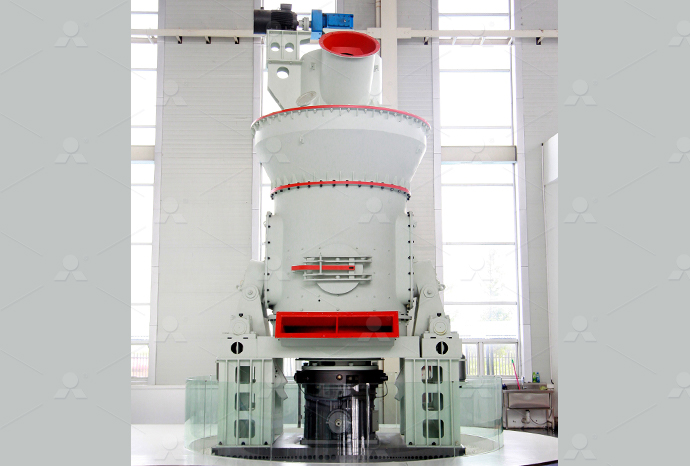
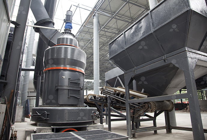
LM Vertical Roller Mill
Input size:38-65mm
Capacity: 13-70t/h
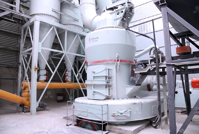
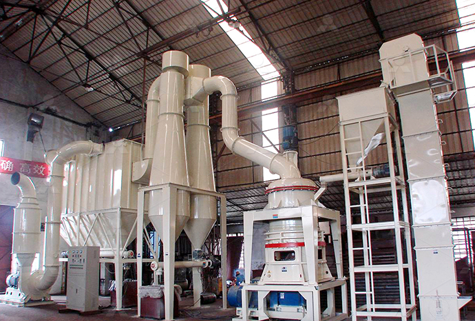
Raymond Mill
Input size:20-30mm
Capacity: 0.8-9.5t/h
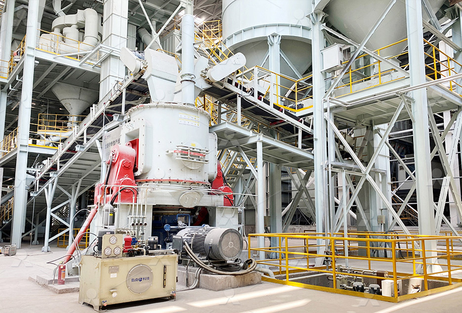
Sand powder vertical mill
Input size:30-55mm
Capacity: 30-900t/h
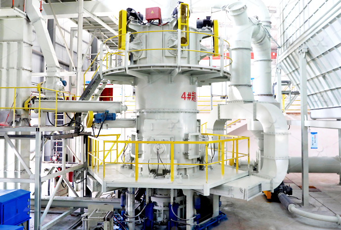
LUM series superfine vertical roller grinding mill
Input size:10-20mm
Capacity: 5-18t/h
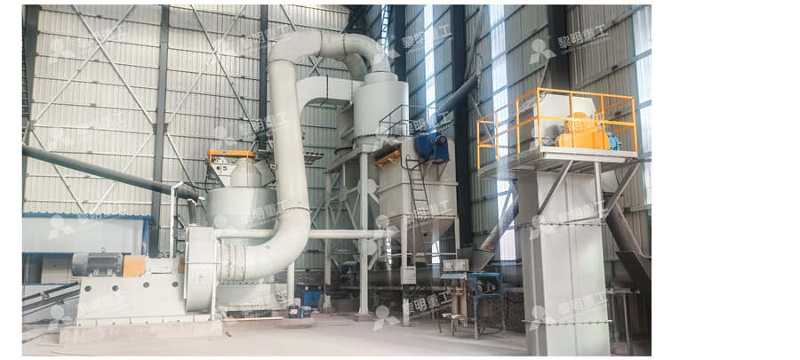
MW Micro Powder Mill
Input size:≤20mm
Capacity: 0.5-12t/h

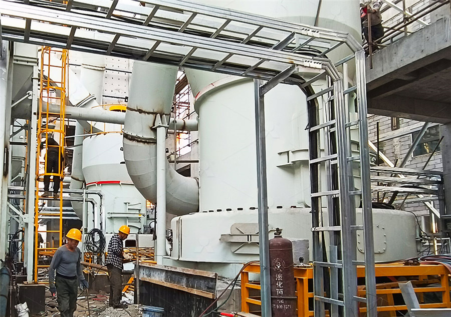
LM Vertical Slag Mill
Input size:38-65mm
Capacity: 7-100t/h
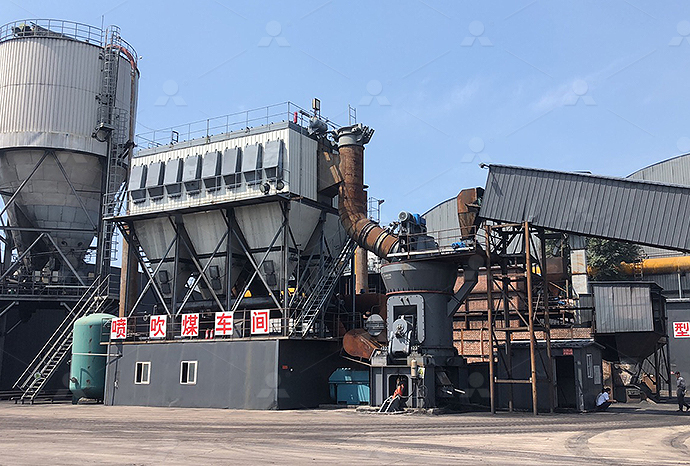
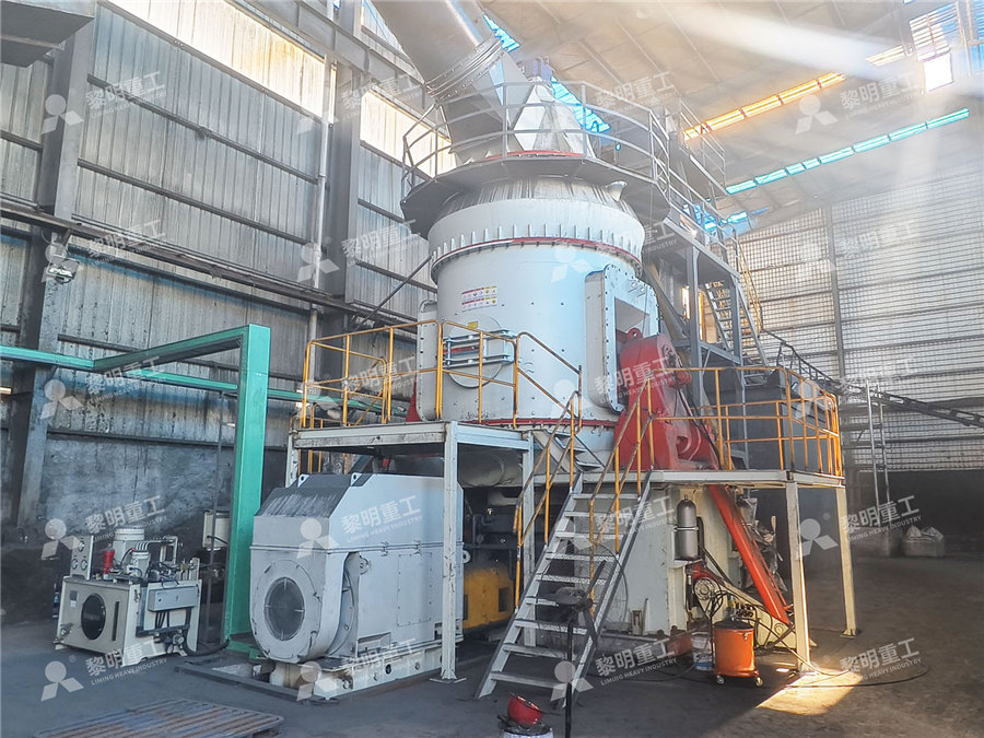
LM Vertical Coal Mill
Input size:≤50mm
Capacity: 5-100t/h
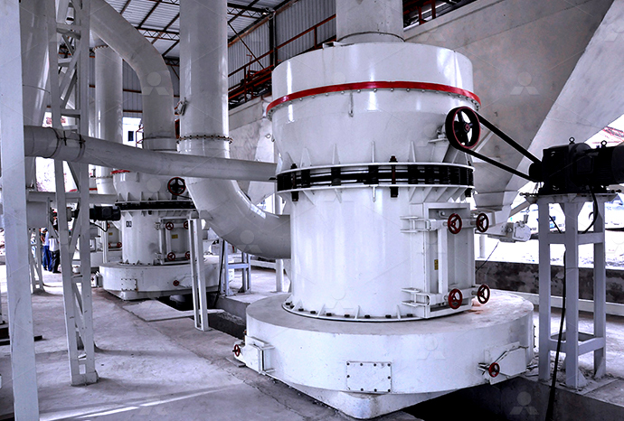
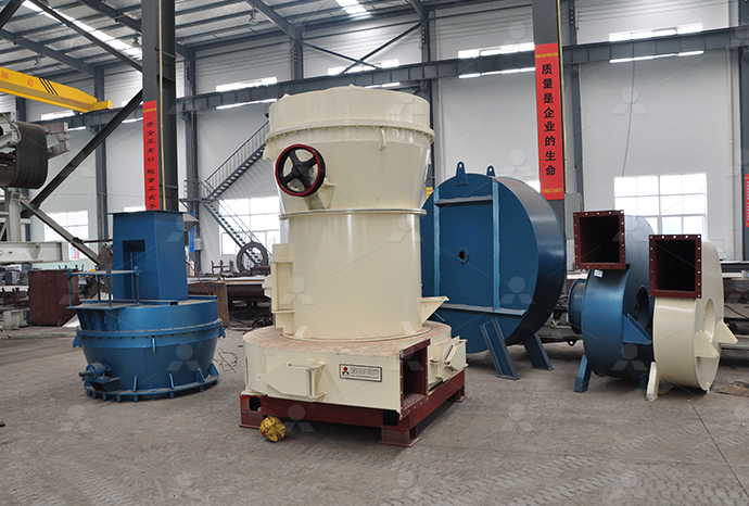
TGM Trapezium Mill
Input size:25-40mm
Capacity: 3-36t/h
MB5X Pendulum Roller Grinding Mill
Input size:25-55mm
Capacity: 4-100t/h

Straight-Through Centrifugal Mill
Input size:30-40mm
Capacity: 15-45t/h
Hitachi powder concentrator capacitor connection circuit diagram
.jpg)
Electromagnetically Compatible Installation Guide Book
HF interference results from rapid switching of electric currents and voltages All AC, DC and servo drives very rapidly switch large currents and voltages to optimally supply connected Onestopshop: Hitachi Energy's capacitor and filter portfolio consists of capacitors and controllers, shunt reactive power compensation banks with and without reactors, stepped and Capacitor and filter product offerings Hitachi EnergyPage 24 Several APCQ capacitor banks can be connected in parallel All APCQ capacitor banks are master units (ie fitted with a RVC or RVT controller) for better availability If two units or Hitachi APCQ Installation, Operation And Maintenance Instructions2004年6月8日 A oneline diagram of the HVDC system is shown in Fig 2 The specifications of the main equipment of this HVDC project are listed in Table 1 Hitachi supplied the main The 1,400MW KiiChannel HVDC System Hitachi
.jpg)
Power factor controllers RVC Hitachi Energy
Direct connection for all network voltages from 100V to 440V Connection to higher network voltages possible through voltage transformer Power factor controller is a key component for Microprocessor system for balanced threephase/singlephase networks and unbalanced network Individual phase power factor control is available From 07 inductive to 07 Power factor controller RVT Hitachi EnergyView and Download Hitachi RAM71QH5 service manual online RAM71QH5 air conditioner pdf manual downloadHITACHI RAM71QH5 SERVICE MANUAL Pdf Download ManualsLibfacilitate connection of wires with a n Easy contact replacement single spanner (H100C to H600C) n Front indication of nameplate Contact can be removed/replaced by single snap Hitachi Electromagnetic Contactors Switches
Connections and composition of LV/MV/HV capacitor banks
2020年1月27日 High voltage capacitor banks are composed of elementary capacitors, generally connected in several serialparallel groups, providing the required electrical characteristics for Highly reliable, low maintenance switching solution for medium voltage capacitor units and banks The PS is a product family of solid dielectric vacuum switches suitable for use in distribution PS Capacitor Vacuum Switches Hitachi Energy2020年11月26日 Simplified Connection Diagram of a Cfilter and its individual primary components Overall impedance for filter shown in Figure 5 Current split between IL and IR for filter shown in Figure 5(PDF) Application Note: Filter Capacitor Bank 2017年9月18日 Methods And Systems For Monitoring Capacitor Banks Diagram Schematic Image 04 Connection Diagrams For Factor Correction Capacitors Kvar Guide Impulse Voltage Generator Marx Circuit Diagram Working Capacitor Bank Schematic Diagram
Circuit Diagram A Circuit Diagram Maker
Circuit Diagram is a free application for making electronic circuit diagrams and exporting them as images Design circuits online in your browser or using the desktop applicationExamples of circuit diagrams that showcase different circuit configurations and the symbols used in them are explained We will also take a closer look at the components we often come across in circuit diagrams, such as resistors, capacitors, and switches, and explain how they are represented with symbolsUnderstanding Circuit Diagrams Components, Reading Guide In a circuit, a Capacitor can be connected in series or in parallel fashion If a set of capacitors were connected in a circuit, the type of capacitor connection deals with the voltage and current values in that network Capacitors in Series Let us observe what happens, when few Capacitors are connected in SeriesCircuit Connections in Capacitors Online Tutorials Library2024年8月5日 The types of capacitors that are available start with a small, delicate management capacitor that may be used with radio circuits or oscillators In highvoltage power modification and smoothing circuits, metalcantype capacitors are used to a great extent The types of capacitors are categorized as follows, based on their structures:Types of Capacitors: Definition, Diagram, Working, Uses [PDF]
Inverter Circuit Diagram: A Complete Tutorial EdrawMax
This article is all about the inverter circuit diagram Capacitor – 001uF – 1; Resistor – 390k ohm – 1; Resistor – 1k ohm – 2; Now, connect all these symbols by drag or drop according to the circuit diagram illustrated below, or you also use the theories you have2009年11月29日 This diagram shows that the Hitachi regulator on the Yanmar engine is an externally sensed connection As Pete says, ideally this terminal would be connected as close to the battery + as possible In any case it should be connected via a connection which, because it carries a very small current, experiences a minimal voltage drop from the battery terminalWhat's the R connection for on a Yanmar / Hitachi alternator?Capacitor Start Motors are singlephase Induction Motors that employ a capacitor in the auxiliary winding circuit to produce a greater phase difference between the current in the main and the auxiliary windings The name capacitor starts itself shows that the motor uses a capacitor for the purpose of starting The figure below shows the connection diagram of a Capacitor Start MotorCapacitor Start Induction Motor Circuit Globe2024年6月5日 For power factor correction, the capacitor bank is used to connect with the load If the load is a threephase load, the capacitor bank can be connected as a star and delta connection Delta Connected Capacitor Bank Power Factor Correction: What is it? (Formula, Circuit
.jpg)
Inside the capacitor bank panel: Power factor
2022年8月23日 You will learn what it means and how to improve power factor value using capacitor banks and analyze capacitors and reactors control and power circuit diagrams Table of contents: Types of Power; Types of Loads; Wondering how a capacitor can be used to start a singlephase motor? Click here to view a capacitor start motor circuit diagram for starting a single phase motor Also read about the speedtorque characteristics of these motors along with Capacitor Start Motors: Diagram Explanation of 2023年8月17日 Takeaways of Capacitors in AC Circuits Capacitors in AC circuits are key components that contribute to the behavior of electrical systems They exhibit capacitive reactance, which influences the opposition to current flow in the circuit Understanding how capacitors behave in series and parallel connections is crucial for analyzing the circuit The Fundamentals of Capacitors in AC CircuitsCircuit Diagram for the use of motor wiring connection 220 / 380 V 380 / 415 V 6 WIRES CONNECT TO THE POWER SOURCE TO START UP OR STAR 200 / 380 /400 V 12 WIRES CONNECT TO THE POWER SOURCE TO START UP OR STAR Product Inquiry Catalog download (Product catalog is available in PDF format) Question Inquiry; MotorThreePhase Motors : The Wiring Connection and Propelling
Capacitors in Series Circuit Diagram and Formula Electrical Volt
Therefore, when n capacitors of the same capacitance are connected in series, then their equivalent capacitance is given by, Now, let us consider an example to understand how to use these formulae in calculations Voltage across Capacitors The capacitive reactance of the capacitor is frequency dependent, and it opposes the flow of electric current and creates If a circuit contains nothing but a voltage source in parallel with a group of capacitors, the voltage will be the same across all of the capacitors, just as it is in a resistive parallel circuit If the circuit instead consists of multiple capacitors that are in series with a voltage source, as shown in Figure 8211 , the voltage will divide between them in inverse proportion82: Capacitance and Capacitors Engineering LibreTextsWhen it comes to wiring an alternator for your Yanmar or Hitachi engine, having a clear understanding of the diagram is essential The alternator is a crucial part of your engine’s electrical system, as it converts mechanical energy into electrical energy to charge the battery and power various components of your boat or plete Guide: Yanmar / Hitachi Alternator Wiring Diagram Whether it’s a singlephase motor, a dual capacitor setup, or a direct connection to a motor, the right wiring diagram is essential to ensure proper electrical connections and optimal performance Reading a run capacitor wiring diagram may seem overwhelming at first, but it’s actually quite a straightforward processHow to Properly Wire a Run Capacitor: StepbyStep Diagram
A Comprehensive Guide to Wiring a Capacitor Start Motor: Diagram
Once the motor reaches a certain speed, the centrifugal switch opens and disconnects the start capacitor from the circuit To properly wire a capacitor start motor, it is essential to follow the wiring diagram provided by the manufacturer This diagram will indicate the correct connections for the start capacitor, start winding, centrifugal 2024年11月17日 The metal foil and insulation are encased in a protective coating, and two metal leads are used for connecting the foils to an external circuit Some common insulating materials are mica, ceramic, paper, and 82: Capacitors and Capacitance Physics LibreTextsStart Capacitors Start capacitors are very helpful in enhancing the starting torque of a motor allow a motor to be On OFF quickly These capacitors stay within the circuit for a long time to bring the motor rapidly to a fixed speed, which is Capacitor Motor : Circuit, Working, Types Its How do I read a Hitachi alternator wiring diagram? To read a Hitachi alternator wiring diagram, you need to understand the symbols and connections used in the diagram The diagram typically consists of lines representing wires, with symbols indicating various electrical components such as diodes, resistors, and coilsWiring diagram for Hitachi alternator: A stepbystep guide
.jpg)
Connecting a Fan with a Capacitor: A Diagram Guide
When it comes to connecting a fan with a capacitor, it is important to understand the wiring diagram and the role of the capacitor in the circuit A capacitor is an electrical component that stores and releases an electrical charge In a fan circuit, the capacitor is used to control the speed and direction of the fanMultiple connections of capacitors behave as a single equivalent capacitor When a charge Q in a series circuit is removed from a plate of the first capacitor (which we denote as \(Q\)), it must be placed on a plate of the second capacitor (which we denote as \(+Q\)), and so on83: Capacitors in Series and in Parallel Physics LibreTextsThis is a simple illustrated circuit diagram of ceiling fanTo be noted that the wiring diagram is for AC 220V single phase line with single phase ceiling fan motor Here a simple SPST switch is used to supply power or not to the fan motor and a Regulator is used to controlling the fan speedCeiling fan wiring diagram with capacitor connectionHitachi Energy offers a comprehensive range of highvoltage switchgear and breaker solutions up to 1200 kilovolts Cable Accessories Capacitors and Filters Communication Networks Cooling Systems Disconnectors Energy Storage Flexible AC Hitachi Energy showcases the world’s first ecoefficient 420kilovolt circuitbreaker at CIGRE HighVoltage Switchgear and breaker products Hitachi Energy
How to Wire Start and Run Capacitors: Wiring Diagram and
Run capacitors, on the other hand, remain connected to the motor circuit at all times and provide a continuous supply of extra power to enhance motor performance Here is a simple example of a start and run capacitor wiring diagram: Start capacitor: Connect one terminal of the start capacitor to the motor’s start winding terminal2020年1月27日 1 Connections of capacitor banks 11 Delta connection This is the most commonly used connection mode for capacitor banks with voltages lower than 12 kV This configuration, which is used in particular in distribution installations, provides maximum reactive power in minimum dimensionsConnections and composition of LV/MV/HV capacitor banksLowvoltage CLMD capacitors for resolving low power factor and power quality problems Learn more Login Hitachi Energy’s CLMD range of capacitors offers such rugged and flexible building blocks to build such solutions for most challenging environments Connection: 3phase (singlephase available on request) Voltage range: From 220 V Lowvoltage capacitors CLMD Hitachi EnergyBlack capacitor wire connects to a reverse switch at terminal 2 Blue capacitor wire (3µF, 350V) goes into the motor housing Red capacitor wire (35µF, 200V) goes to switch terminal 3 Yellow capacitor wire (6µF, 200V) goes to switch 3 Speed Fan Capacitor Wiring Diagram Circuits
Cbb61 Fan Capacitor Connection » Wiring Diagram
2023年3月25日 Wiring Diagrams for Cbb61 Fan Capacitor Connection The following are some of the wiring diagrams for connecting the Cbb61 fan capacitor: Single Phase Motor Wiring Diagram – This diagram shows how the capacitor With the help of our ceiling fan wiring diagram with capacitor PDF, you can confidently install your ceiling fan and enjoy its benefits in no time Ceiling Fan Wiring Diagram with Capacitor – Complete Guide If you are looking to install A Simple Guide to Ceiling Fan Wiring with CapacitorDirect connection for all network voltages from 100V to 440V Connection to higher network voltages possible through voltage transformer Measurement and display of key parameters (voltage, current, power factor, THDV and THDI) Fully programmable switching sequence; Easy commissioning; Complete auto setup; Easy to use thanks to userfriendly Power factor controllers RVC Hitachi EnergyHitachi Energy’s DC drytype capacitor DryDCap is a dry DC capacitor for modern converter topologies Being dry, there is no risk of leakage, and there is a minimal environmental impact during the product’s entire lifecycle Its high energy density capability allows for compact designs, and it is usable in inhouse and open air installationsDry DClink capacitors (DC) Hitachi Energy

01/BKpg KHWS1 cover
CIRCUIT DIAGRAM Since many parts in the unit have special safetyrelated characteristics, always use genuine Hitachi’s replacement Remarks: Instrument Connection *1: With a 470 µF/63 V capacitor to the TP2 () and J209/+B(+) "IC202" *2: Mean Note 2 (See page 17)The wiring diagram helps in connecting the capacitor to the electrical circuit correctly, A capacitor is an electronic component that stores electrical energy and helps regulate the flow of current in a circuit In a 4wire capacitor wiring diagram, you will typically see 4 terminals labeled “C,” “H,” “F,” and “C,” which How to Connect a 4 Wire Capacitor: Wiring Diagram and StepsOverall, the capacitor discharge ignition system diagram illustrates the various components and their connections, highlighting the important role each component plays in the ignition process Understanding this diagram can help mechanics and enthusiasts troubleshoot ignition issues and ensure efficient and reliable engine performanceExploring the Capacitor Discharge Ignition System DiagramConnection of fan circuit diagram with capacitor Table Fan, (affiliate)Havells Leganza 1200mm Ceiling Fan Connection of fan circuit diagram with capacitor Table Fan, Connection of fan circuit diagram with capacitor YouTube