


HOME→Schematic diagram of electromagnetic vibration controller Schematic diagram of electromagnetic vibration controller Schematic diagram of electromagnetic vibration controller
MTW European Type Trapezium Mill
Input size:30-50mm
Capacity: 3-50t/h
LM Vertical Roller Mill
Input size:38-65mm
Capacity: 13-70t/h

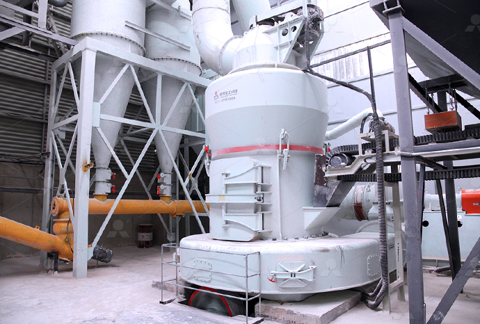
Raymond Mill
Input size:20-30mm
Capacity: 0.8-9.5t/h

Sand powder vertical mill
Input size:30-55mm
Capacity: 30-900t/h

LUM series superfine vertical roller grinding mill
Input size:10-20mm
Capacity: 5-18t/h

MW Micro Powder Mill
Input size:≤20mm
Capacity: 0.5-12t/h

LM Vertical Slag Mill
Input size:38-65mm
Capacity: 7-100t/h

LM Vertical Coal Mill
Input size:≤50mm
Capacity: 5-100t/h
TGM Trapezium Mill
Input size:25-40mm
Capacity: 3-36t/h

MB5X Pendulum Roller Grinding Mill
Input size:25-55mm
Capacity: 4-100t/h

Straight-Through Centrifugal Mill
Input size:30-40mm
Capacity: 15-45t/h
Schematic diagram of electromagnetic vibration controller Schematic diagram of electromagnetic vibration controller Schematic diagram of electromagnetic vibration controller

Schematic of the electromagnetic vibration energy
Download scientific diagram Schematic of the electromagnetic vibration energy harvester: (a) overall structure; (b) magnet and coil arrays from publication: A Nonlinear ElectromagneticThis paper deals with an optimization study of a vibration energy harvester This harvester can be used as autonomous source of electrical energy for remote or wireless applications, which areSchematic diagram of electromagnetic vibration This paper deals with the efficiency analysis of developed electromagnetic vibration energy harvesting systems The efficiency analysis of this energy harvesting system is specified and a linearSchematic diagram of vibration energy harvesting system2022年2月1日 This paper proposed an electromagnetic vibration energy harvester using an innovative vibrationtorotation conversion mechanism based on a magnet array A magnet An electromagnetic vibration energy harvester using a magnet

Linear electromagnetic electric generator for harvesting vibration
2016年11月30日 This study proposes a linear electromagnetic generator that can harvest vibration energy from a transformer and supply electricity to a monitoring system The sensor 2019年7月23日 In this section, the implement process of realtime controllable electromagnetic vibration isolator with QZS characteristic is presented in detail, which includes three parts: the A realtime controllable electromagnetic vibration isolator based 2022年10月31日 To effectively suppress the electromagnetic vibration generated by a permanent magnet motor at different frequency bands and to further improve the Optimization of sideband electromagnetic vibration and Aimed at this problem, a novel active control strategy with a double closedloop PID algorithm was designed in this paper The double closedloop strategy includes an internal and external loop Vibration Isolation of Magnetic Suspended Platform with Double
.jpg)
Schematic diagram of the whole vibration power
This paper presents an integrated vibration power generator system The system consists of a mini electromagnetic vibration power generator and a highly efficient energy harvesting circuitOne of the most essential skills for an electrical engineer is the ability to read and create schematics Before you start learning Ohm’s law, superposition theorem, and deltawye transforms, you need a basic understanding of how to read The Schematic Diagram: A Basic Element of Circuit Download scientific diagram Schematic diagram of electromagnetic generator from publication: Optimization of an Electromagnetic Energy Harvesting Device This paper presents the modeling and Schematic diagram of electromagnetic generatorDownload scientific diagram Schematic diagram of an electromagnetic field and electromagnetic force from publication: A MultiPhysics ModelingBased Vibration Prediction Method for Switched Figure 2 Schematic diagram of an electromagnetic

Electromagnetic Braking System Circuit Diagram
2017年11月17日 An electromagnetic braking system is composed of a controller, three speeds, and a circuit diagram The controller monitors the speed of the car and activates the electromagnetic brakes when needed In order to Download scientific diagram Detailed schematic diagram of the stimulator from publication: A Dual Mode Pulsed ElectroMagnetic Cell Stimulator Produces Acceleration of Myogenic Differentiation Detailed schematic diagram of the stimulator2018年7月6日 To understand how a crane works, let's take a look at the electromagnetic crane circuit diagram An electromagnetic crane consists of an alternator, Actuators Free Full Text Research On An Electromagnetic Actuator For Vibration Suppression And Energy Regeneration 182 Magnetic Crane Controller Wiring O Gauge Railroading On Electromagnetic Crane Circuit Diagram Wiring Digital and SchematicDownload scientific diagram Schematic of the electromagnetic levitation system from publication: Nonlinear vibration and control of maglev vehicleswitch beam coupling system The electro Schematic of the electromagnetic levitation system
.jpg)
Exploring the Inner Workings of an Xbox Controller: A Detailed
A Detailed Schematic Diagram A schematic diagram is a visual representation of the components and connections within a device, providing a detailed overview of its inner workings In the case of an Xbox controller, a detailed schematic diagram is a valuable resource for understanding how the controller operates and how each button and Download scientific diagram Experiment table: (a) schematic diagram of the active vibration control of motorized spindle systems; and (b) experiment table layout from publication: Active Experiment table: (a) schematic diagram of the active vibration Download scientific diagram Schematic diagram of magnetic levitation system from publication: Modeling and nonlinear control of magnetic levitation system In this paper, the authors propose a Schematic diagram of magnetic levitation systemDownload scientific diagram Schematic outlines of electromagnetic force compensation (EMFC) balancetype scale from publication: Effect of Electromagnetic Damping on System Performance of Voice Schematic outlines of electromagnetic force compensation

6: Basic schematic diagram of the electromagnet
Download scientific diagram 6: Basic schematic diagram of the electromagnet driver circuit; which consists of a variable autotransformer (VARIAC), a step up transformer, a rectifier diode (D), a 2017年11月16日 In the context of circuit diagrams, electromagnetic levitation refers to a series of circuits that act together to create a stable, responsive and safe system of lifting a load using magnetic forces The key components of an Electromagnetic Levitation Circuit Diagram Wiring Download scientific diagram Schematic diagram of the whole vibration power generator system from publication: Electromagnetic Energy Harvesting Circuit With Feedforward and Feedback DC–DC PWM Schematic diagram of the whole vibration power An AC motor control circuit diagram is a schematic representation of the connections and components used in an electrical system to control the operation of an AC motor It shows how the various control devices, such as switches, relays, and contactors, are connected to the motor to start, stop, and change its direction of rotationAc Motor Controller Schematic: Understanding the Basics and
.jpg)
How To Read And Interpret Schematic Diagrams
2018年9月8日 What Is The Meaning Of Schematic Diagram Sierra Circuits How To Read Cellphones Schematic Diagrams Under Repository Circuits 21994 Next Gr How To Read Car Wiring Diagrams For Beginners Emanualonline Blog Reading And Interpreting Schematic Diagrams How To Read An Electrical Diagram Instrumentation And Control Engineering2021年10月9日 Electromagnetic Waves The Diagram Of Electromagnetic Wave Constructed Through Regimentation Electric Field And Magnetic Measurement Of Electromagnetic Waves Emitted By Mobile Phones In Scientific Diagram 5 A Prinl Sketch Of An Electromagnetic Wave Scientific Diagram 6 Basic Schematic Diagram Of The Electromagnet Driver Circuit Which Simple Circuit Diagram Of An Electromagnetic Wave2023年3月16日 Main And Auxiliary Circuit Diagrams Of Switching Three Phase Motors Via Contactor Directly Eep Usfull Nlc1 D Ac Contactor Electrical Contactor Connection And Wiring 1 Bbe Electrical Circuit Diagram Facebook Volume 10 Tab 4 Outdoor Wiring With Magnetic Contactor Diagram Fully4world Contactors And Relays Construction OperationContactor Schematic DiagramDownload scientific diagram 1 Schematic Diagram of Principle of Electromagnetic Braking System from publication: STUDY AND FABRICATION OF ELECTROMAGNETIC BRAKING SYSTEM ResearchGate, the 1 Schematic Diagram of Principle of Electromagnetic Braking
.jpg)
Typical control schematic diagram of magnetic bearing system
Download scientific diagram Typical control schematic diagram of magnetic bearing system from publication: Resonance Vibration Control for AMB Flexible Rotor System Based on µ Synthesis A typical schematic line diagram of the electromagnetic forming (EMF) system used in the experiments is shown in Fig 2 Figure 3 shows various components of the EMF systemSchematic line diagram of circuit of electromagnetic formingDownload scientific diagram Schematic diagram of a PMDC commutator motor from publication: TwoDimensional Field Analysis on Electromagnetic VibrationandNoise Sources in PermanentMagnet Schematic diagram of a PMDC commutator motorDownload scientific diagram Schematic block diagram of the proposed controller design from publication: Vibration Control of Truck Cabins With the Adaptive Vectorial Backstepping Design of Schematic block diagram of the proposed controller
.jpg)
BLDC Motor Controller: Design Principles Circuit
2021年2月25日 So in a BLDC motor controller circuit diagram, this will look like two or three halfbridges (depending on the number of phases) with a pair of switches each Let’s take a closer look at a 3 phase brushless DC motor Download scientific diagram Schematic diagram of EMS maglev system from publication: The Most Important Maglev Applications The name maglev is derived from magnetic levitation Magnetic Schematic diagram of EMS maglev system ResearchGate2017年11月16日 The circuit diagram of an electromagnetic pendulum consists of several electrical connections, each of which must be properly connected in order for the pendulum to respond correctly These components include capacitors, resistors, transistors, transformers, and other componentsElectromagnetic Pendulum Circuit DiagramDownload scientific diagram Schematic diagram of electromagnetic sheet forming process from publication: Dynamic analysis of electromagnetic sheet metal forming process using finite element Schematic diagram of electromagnetic sheet forming process
CFB石灰石脱硫剂制备——磨机公众号12.8 推送案例(8)53.jpg)
Schematic diagram of electromagnetic vibration energy
Download scientific diagram Schematic diagram of electromagnetic vibration energy harvester model from publication: Artificial intelligence optimizes ambient vibration energy harvesting Download scientific diagram Schematic Diagram of Magnetic Levitation System from publication: Nonlinear Model Controller Design for Magnetic Levitation System This paper aims at development Schematic Diagram of Magnetic Levitation SystemElectromagnetic forming has attracted more and more attention in the advanced manufacturing field as a promising technology to improve the formability of lightweight alloys at room temperatureThe schematic diagram of the electromagnetic formingThe schematic diagram of the feedback control system is depicted in Fig 6 [20] propose also a sliding mode controller for vibration control of a beam with piezoelectric transducersSchematic diagram of vibration control experiment
.jpg)
Schematic diagram of ASIC control system
Download scientific diagram Schematic diagram of ASIC control system comprising controller circuit, electromagnetic valves and micro RT–PCR chip Note that the control system is operated by a Download scientific diagram The schematic diagram of Electromagnetic field circuit from publication: A Novel Electromagnetic Field Detector for Extremely Low Frequency Energy Electromagnetic The schematic diagram of Electromagnetic field circuitSystem overview Figure 1(a) shows a schematic diagram of the entire vibration isolation system on the base slab The laboratory is located on the first floor of a fivestory building (625 m  27 (Color online) Schematic diagrams of the entire Download scientific diagram Schematic diagram of electromagnetic flowmeter When the conductive fluid flows through the pipe at an average flow rate v , the fluid cuts the magnetic field B , then Schematic diagram of electromagnetic flowmeter When the
.jpg)
Simulation Analysis and Optimization of Electromagnetic Vibration
2024年1月9日 Motor vibration and noise are two of the most important indicators of the quality of a motor More often than not, motor vibration is caused by the radial electromagnetic force in the air gap [1,2,3,4] and is transmitted to the stator surface through the stator teeth [5,6,7]In practice, the severity of the vibration and noise increases as the vibration frequency approaches the 2024年10月4日 More simply, a schematic diagram is a simplified drawing that uses symbols and lines to convey important information For example, if you are taking the subway you may see a “map” showing you all the stations along a subway line, but that map will not show all the roads and buildings you may pass along the wayWhat Is a Schematic Diagram? ThoughtCoIn this paper, a highperformance feedback controller for an electromagnetic vibratory feeder is proposed An electromagnetic actuator is driven by a switching circuit with pulsewidth as the Typical construction of a vibratory feeder (conveyor) with an Download scientific diagram 1: Schematic of an electromagnetic actuator from publication: Unbalance Compensation by Active Magnetic Bearings Active magnetic bearings are used in many highend 1: Schematic of an electromagnetic actuator Download Scientific Diagram
.jpg)
The Ultimate Guide: Understanding the Magnetic Contactor Circuit Diagram
A magnetic contactor circuit diagram is a visual representation of the electrical connections and components used in a magnetic contactor It shows how power is supplied to the contactor coil and how the contacts are connected to control the flow of electricity This diagram is useful for understanding the functionality and troubleshooting of magnetic contactorsDownload scientific diagram PID block diagram and the circuit schematic of PID controller from publication: Design of a ClosedLoop, Bidirectional Brain Machine Interface System With Energy PID block diagram and the circuit schematic of PID controller