


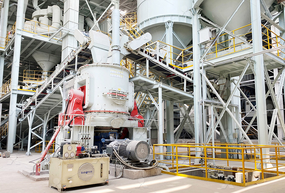
MTW European Type Trapezium Mill
Input size:30-50mm
Capacity: 3-50t/h
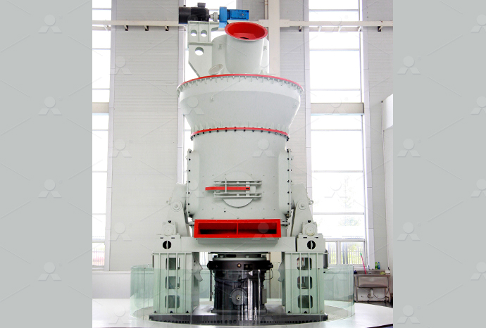
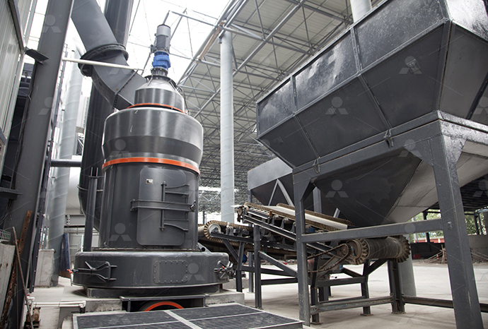
LM Vertical Roller Mill
Input size:38-65mm
Capacity: 13-70t/h
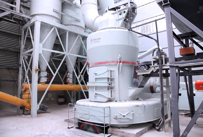
Raymond Mill
Input size:20-30mm
Capacity: 0.8-9.5t/h
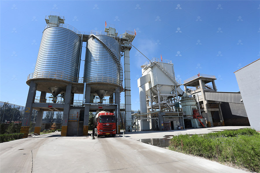
Sand powder vertical mill
Input size:30-55mm
Capacity: 30-900t/h
LUM series superfine vertical roller grinding mill
Input size:10-20mm
Capacity: 5-18t/h
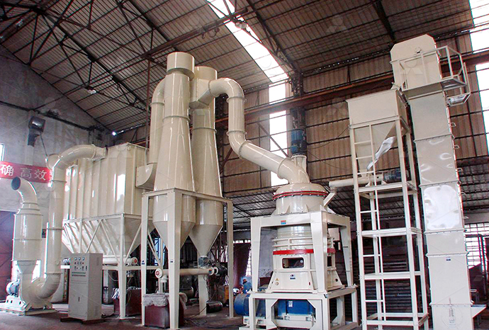
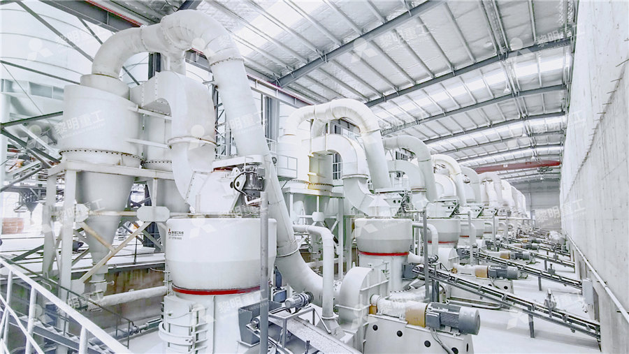
MW Micro Powder Mill
Input size:≤20mm
Capacity: 0.5-12t/h

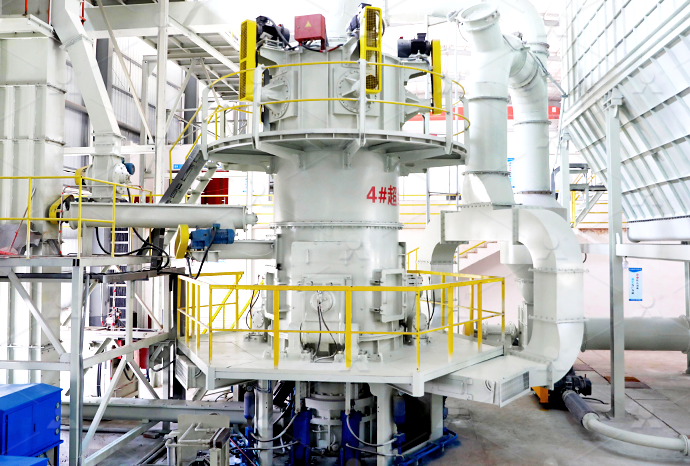
LM Vertical Slag Mill
Input size:38-65mm
Capacity: 7-100t/h
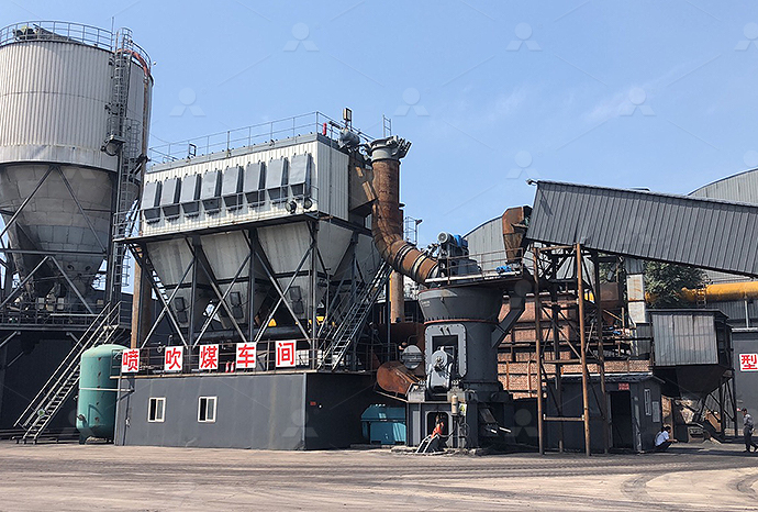
LM Vertical Coal Mill
Input size:≤50mm
Capacity: 5-100t/h
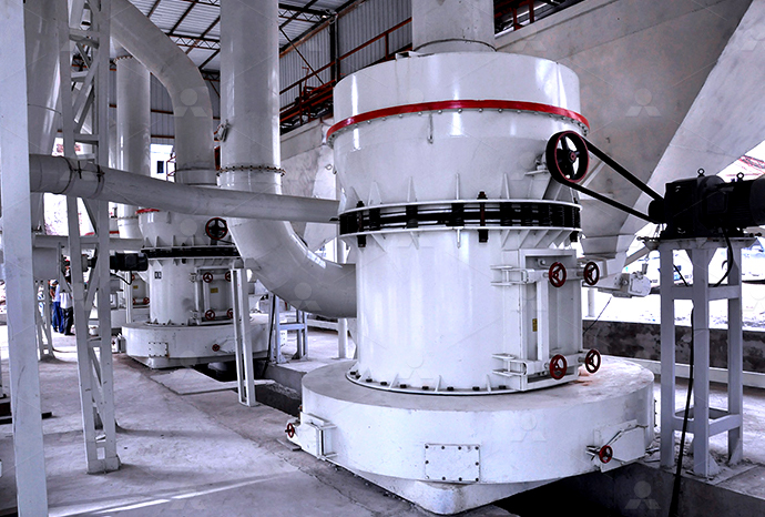
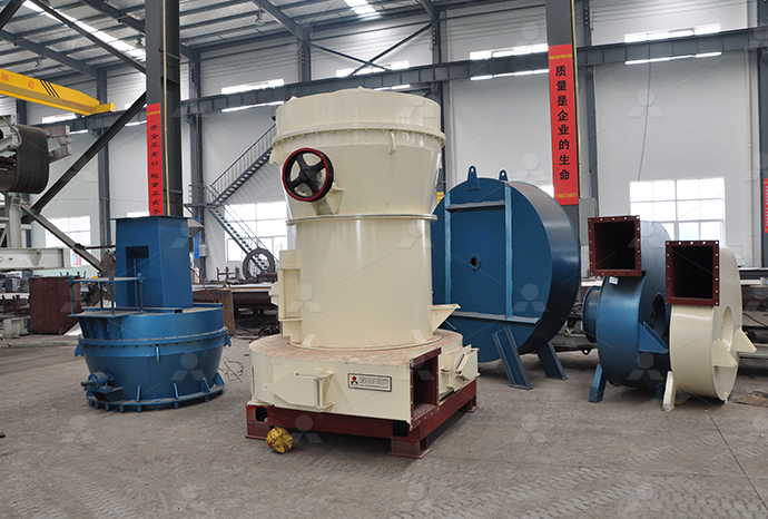
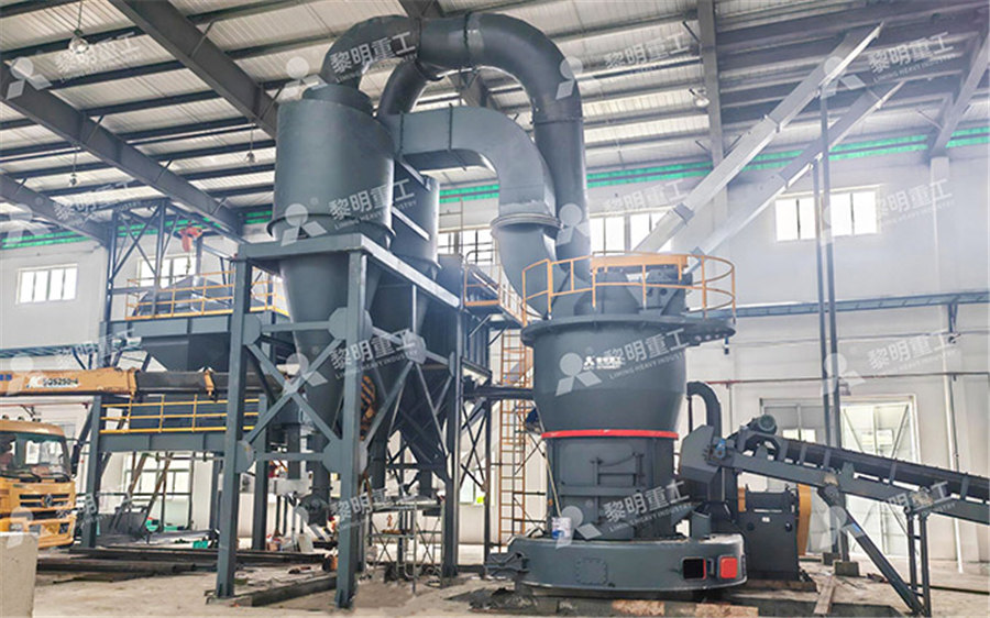
TGM Trapezium Mill
Input size:25-40mm
Capacity: 3-36t/h
MB5X Pendulum Roller Grinding Mill
Input size:25-55mm
Capacity: 4-100t/h

Straight-Through Centrifugal Mill
Input size:30-40mm
Capacity: 15-45t/h
Spherical mechanism motion diagram
.jpg)
Atlas of spherical fourbar mechanisms ScienceDirect
2011年11月1日 The typical spherical fourbar mechanism is shown in Fig 2 It comprises three moving links: the crank AB, the coupler BC, and the driven link CD The pivots A and D are A novel spherical gripper mechanism (SGM) with one degree of freedom was designed This gripper consists of a network of spherical parallelogram mechanisms Design limits, work spaceSpherical mechanism design Download Scientific Fig 1 illustrates a four revolute spherical mechanism The fixed (grounded) pivots are represented by unit vectors a 0 and b 0 The moving pivots are represented by unit vectors a 1 and b 1 Spherical mechanism with fixed pivot, moving pivot 2022年4月5日 In this paper, a novel twodegreeoffreedom (2DOF) SPM with symmetrical structure is proposed and analyzed First, the models of forward kinematics and inverse Motion Characteristics Analysis of a Novel Spherical Twodegree
.jpg)
Example 3: Infinity fan driven by a spherical fourbar
This paper studies the problem of spherical fourbar motion synthesis from the viewpoint of acquiring circular geometric constraints from a set of prescribed spherical poses The2021年5月9日 Figure 1 shows the kinematic diagram of a coaxial spherical parallel mechanism 3RRR, which is formed using three limbs with coaxial active joints connecting a mobile Kinematic Analysis of a Coaxial 3RRR Spherical Parallel SpringerThe paper presents a parametric form of EulerSavary equations for spherical instantaneous kinematics The formulation procedures are explained for Ball and BallBurmester points The Kinematics of Spherical Mechanisms Semantic ScholarSpherical mechanisms are identified as the method by which most action origami models achieve complicated motion while remaining flatfoldable The subset of action origami whose motion Study of Action Origami as Systems of Spherical Mechanisms
.jpg)
Concept And Design Of A Spherical Joint Mechanism For
2018年1月1日 To meet these, in this paper, a mechanism similar to a spherical joint is proposed and compared to others It can be used to extend the workspace of manipulators and add a Download scientific diagram Spherical double Scotch yoke: ( a ) kinematic diagram; ( b ) concept of the associated flapping mechanism, see also figure 6 from publication: Insectlike flapping Spherical double Scotch yoke: ( a ) kinematic Download scientific diagram The motion of human ankle joint from publication: An ankle rehabilitation robot based on 3RRS spherical parallel mechanism This article presents the design The motion of human ankle joint Download Scientific 2023年1月9日 Cams and followers mechanisms are primarily used in the internal combustion engine to operate the valves Also, the cam and follower mechanism is often used by engineers as a part of the ICE timing system Cam and Follower: Definition, Types, Working Uses
Cam and Follower : Types , Diagram , Parts , Working
A cam and follower are a method of converting rotary motion into linear motion The most wellknown application is in an internal combustion engine, Spherical Cams In this cam, it again rises Follower displacement and cam angle diagram for this type of cam is shown in Figure 155(a) Dwell, Risereturn Dwell 2021年5月9日 Figure 1 shows the kinematic diagram of a coaxial spherical parallel mechanism 3RRR, which is formed using three limbs with coaxial active joints connecting a mobile platform to a fixed base All the joint axes of the mechanism are concurrent in the origin O of the fixed XYZ reference frame, which is referred to as the center of rotation The mobile platform has Kinematic Analysis of a Coaxial 3RRR Spherical Parallel SpringerKINEMATICS OF MACHINERY SCE 2 Department of Mechanical Engineering • Examples of mechanisms: Tin snips, vise grips, car suspension, backhoe, piston engine, folding chair, windshield wiper drive system, etc Key concepts: • Degrees of freedom: The number of inputs required to completely control a system Examples: A simple rotating linkKINEMATICS OF MACHINERY UNIT I BASICS OF MECHANISMS 9 Download scientific diagram Spherical mechanism design from publication: ComputerAided Modeling and Manufacturing of Spherical Mechanisms via a Novel Web Tool In this paper, we present a Spherical mechanism design Download Scientific Diagram
Motion generation of spherical fourbar mechanism using
2016年1月1日 In reference [20], we discussed the relationship between coupler curve of the spherical fourbar mechanism and its harmonic composition; determined the basic dimensional type of spherical fourbar mechanism; deduced the theoretical formula which may compute the position for coupler point, true size, and installing dimensions of the spherical fourbar A novel 3degreesoffreedom (DOF) spherical mechanism, singularityfree in the anatomical shoulder joint workspace, is described The use of curved scissors linkages interconnected by revolute (A) The original configuration of the spherical shoulder mechanism Download scientific diagram Spherical four bar mechanism from publication: On the Derivation of the Coordinates of Coupler Points in Spherical Mechanisms In great number of applications the Spherical four bar mechanism Download Scientific DiagramDownload scientific diagram A PLANAR FOURBAR MECHANISM from publication: A classification scheme for planar 4R, spherical 4R, and spatial RCCC linkages to facilitate computer animation In A PLANAR FOURBAR MECHANISM Download
.jpg)
(A) The configuration of the spherical scissor
Download scientific diagram (A) The configuration of the spherical scissor mechanism with one rhombus still interferes with the upper arm anatomy by penetrating within its volume; (B) Therefore Design and Analysis of a Spherical Joint Mechanism for Robotic 99 Fig 8 Stress analysis 10 Conclusion and Future Scope This study proposes a new spherical joint mechanism based on linear actuators This mechanism can actively drive the three R Design and Analysis of a Spherical Joint Mechanism forpurpose of this mechanism is to convert rotary motion into reciprocating motion Coupling rod of a locomotive (D ouble Crank mechanism) The mechanism of a coupling rod of a locomotive which consists of 4 links is shown in Figure In this mechanism, the links AD and BC (h aving equal length) act as crank and are connected to the respective wheelsUNIT 1 BASICS OF MECHANISMS Sathyabama Institute of Download scientific diagram Example 2: The resulting spherical fourbar mechanism constructed by p 1 and p 4 from publication: A Unified Approach to Exact and Approximate Motion Synthesis of Fig 7 Example 2: The resulting spherical fourbar mechanism
Spherical rolling robots—Design, modeling, and control: A
2024年5月1日 Spherical robots possess a distinctive motion mechanism, resulting in intricate kinematics and dynamics to model and analyze The incorporation of nonholonomic constraints, as discussed in Section 31, further amplifies the complexity of these models2022年12月1日 Moreover, the rotational characteristics of the mechanism are proved, and motion planning is carried out A numerical example is given to verify the kinematics analysis and motion planningMotion Characteristics Analysis of a Novel Spherical Twodegree Download scientific diagram The spherical fourbar and geometric construction of a Burmester curve for four prescribed positions during motion generation in a spherical mechanismThe spherical fourbar linkage Download Scientific DiagramDownload scientific diagram Actuation mechanism of a spherical robot allowing omnidirectional motion from publication: Nonlinear optimal control for a spherical rolling robot The article Actuation mechanism of a spherical robot allowing omnidirectional motion
Schematic representation of several mechanisms with a
Download scientific diagram Schematic representation of several mechanisms with a remote center of motion that can satisfy the pivot point constraint from publication: Design of a compact 5DOF Download scientific diagram Mechanical design (a) and section (b) of the lockable spherical joint from publication: Details on the Design of a Lockable Spherical Joint for Robotic Applications Mechanical design (a) and section (b) of the lockable 2018年8月13日 The spherical joint is one of the main motion pairs in spatial parallel mechanism, and the spherical clearance has a great effect on the nonlinear dynamic performance of parallel mechanism Most previous studies mainly focused on planar mechanism with revolute joint, spatial parallel mechanism with spherical clearance researched rarely In this paper, the Chaotic characteristic analysis of spatial parallel mechanism Download scientific diagram Example 3: Infinity fan driven by a spherical fourbar mechanism from publication: A Task Driven Approach to the Synthesis of Spherical 4R Linkages Using Algebraic Example 3: Infinity fan driven by a spherical fourbar
Four revolute spherical motion generator with rigid body
Download scientific diagram Four revolute spherical motion generator with rigid 1984), a synthesis method for the function, path and motion generation of spherical mechanisms as indicated Download scientific diagram A threerevolute spherical wrist as a pointing mechanism from publication: Contributions to the kinematics of pointing Pointing consists in orienting a line OP of a A threerevolute spherical wrist as a pointing mechanismDownload scientific diagram Spherical serial mechanism with coordinate assignment (ℜ i (x i , y i , z i )) from publication: A design of slave surgical robot based on motion capture The Spherical serial mechanism with coordinate assignment (ℜ i (x Download scientific diagram Prototype of a new active ball joint mechanism, ABENICS from publication: ABENICS: Active Ball Joint Mechanism With ThreeDoF Based on Spherical Gear Meshings This Prototype of a new active ball joint mechanism, ABENICS
Spherical serial two link mechanism (a) link and joint assignment
Download scientific diagram Spherical serial two link mechanism (a) link and joint assignment based on the DenavitHartenberg (DH) notation (b) the mechanism DH parameter notation summary where 2016年5月26日 llustrates a process diagram leading ultimately to cam mechanism design As this figure illustrates, given a group of prescribed coupler positions, the spherical fourbar motion generation model Spherical fourbar motion generation and axode generation in Download scientific diagram Bevel gear mechanism for the lockable spherical joint from publication: Details on the Design of a Lockable Spherical Joint for Robotic Applications The paper Bevel gear mechanism for the lockable spherical jointSpherical Geneva Mechanism: In this type of mechanism the Geneva cross is in spherical shape and cam drives are connected in externally, which is extremely rare and is illustrated in below fig4 Internal Geneva Mechanism Fig4 Spherical Geneva
Kinematic solution of spherical StephensonIII sixbar mechanism
2013年9月28日 A closedform solution can be obtained for kinematic analysis of spatial mechanisms by using analytical method However, extra solutions would occur when solving the constraint equations of mechanism kinematics unless the constraint equations are established with a proper method and the solving approach is appropriate In order to obtain a kinematic Download scientific diagram Fivebar spherical metamorphic mechanism from publication: Matrix Representation of Topological Changes in Metamorphic Mechanisms Metamorphic mechanisms form a Fivebar spherical metamorphic mechanismDownload scientific diagram Rotation center in two planar–spherical motion generators from publication: 1T2R Parallel Mechanisms Without Parasitic Motion Motion Synthesis, Parallel and Rotation center in two planar–spherical motion generatorsDownload scientific diagram A general 5R spherical parallel manipulator (17) are satisfied, and Δ2 equals 0, and the motion of the proposed spherical mechanisms is impeded The precise A general 5R spherical parallel manipulator ResearchGate
Prototype of the mechanism Download Scientific Diagram
Download scientific diagram Prototype of the mechanism from publication: Modeling of a Remote Center of Motion Spherical Parallel Tensegrity Mechanism for Percutaneous Interventions The 2023年8月20日 The connectivity of the links and joints in the mechanism is expressed in a kinematic diagram (Fig 5) rather than the dimensions or shapes of the elements The stroke lengths of the four linear actuators ( J 1, J 2, J 3, and J 4) are set relative to the position of the top mount required in the workspaceDesign and Analysis of a Spherical Joint Mechanism for Robotic Download scientific diagram Fourbar spherical mechanisms from publication: Reliability analysis of spherical function generating mechanisms Spherical mechanisms are widely used in engineering Fourbar spherical mechanisms Download Scientific DiagramDownload scientific diagram [30] of spherical fourbar mechanisms In the motion generation dimensional synthesis of spherical fourbar mechanisms, sequential quadratic programming Scalar difference plots between prescribed and achieved rigid
CAD model of spherical five bar mechanism Download Scientific Diagram
Download scientific diagram CAD model of spherical five bar mechanism from publication: Comparison of Workspace Analysis for Different Spherical Parallel Mechanisms: Proceedings of the 4th