


MTW European Type Trapezium Mill
Input size:30-50mm
Capacity: 3-50t/h
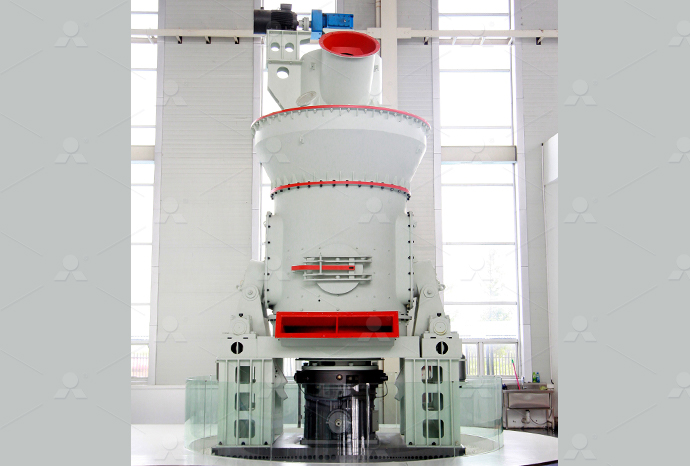
LM Vertical Roller Mill
Input size:38-65mm
Capacity: 13-70t/h
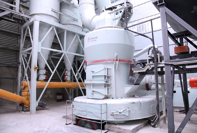
Raymond Mill
Input size:20-30mm
Capacity: 0.8-9.5t/h
Sand powder vertical mill
Input size:30-55mm
Capacity: 30-900t/h
LUM series superfine vertical roller grinding mill
Input size:10-20mm
Capacity: 5-18t/h
MW Micro Powder Mill
Input size:≤20mm
Capacity: 0.5-12t/h

LM Vertical Slag Mill
Input size:38-65mm
Capacity: 7-100t/h
LM Vertical Coal Mill
Input size:≤50mm
Capacity: 5-100t/h
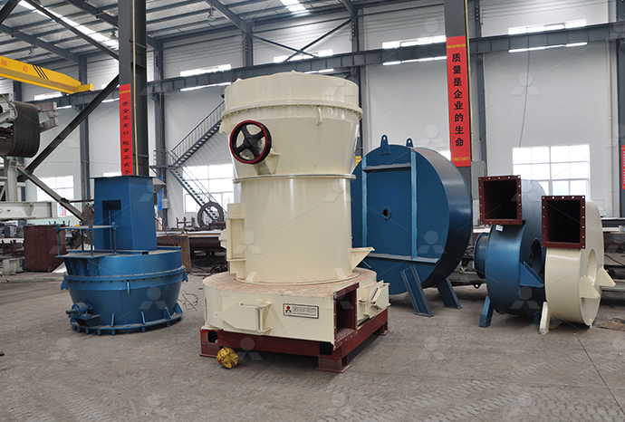
TGM Trapezium Mill
Input size:25-40mm
Capacity: 3-36t/h
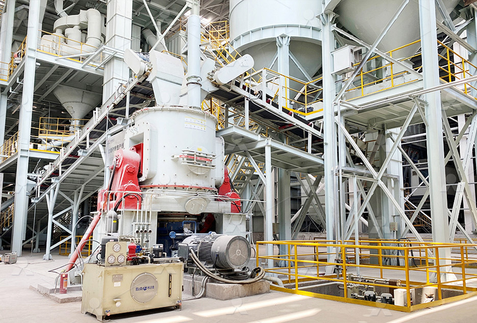
MB5X Pendulum Roller Grinding Mill
Input size:25-55mm
Capacity: 4-100t/h

Straight-Through Centrifugal Mill
Input size:30-40mm
Capacity: 15-45t/h
Waterthrust reducer
.jpg)
27 Thrust Restraint Design for Buried Piping WSSC Water
In a pressurized buried pipeline such as a water main or sewage force main, thrust forces act on the pipe where changes in fluid velocity, changes in pipe size or changes in pipeline direction REDUCERS The unbalanced force is generated by the pressure acting on the difference in cross sectional area between the large and small side of the reducer This may be opposed by THRUST RESTRAINT DESIGN OF DEAD ENDS, VALVES, REDUCERS, 2021年4月27日 A thrust block is a concrete pipe restraint that prevents the mainline from moving by transferring pipe loads (mainly due to pressure thrust) to a wider loadbearing surface Usually, thrust blocks are provided for buried What is a Thrust Block? It’s Design, Construction, REDUCERS In any water distribution or wastewater force main system, regardless of the pipe material, the mechanical joint reducer will be common The restrained length calculation for Thrust Restraint Design of Reducers, Dead Ends, and Valves EBAA
.jpg)
(PDF) Thrust block design Shubham Jain Academia
Thrust blocks and restraint joints are the two most popular methods of counteracting the thrust force that generated at pipe fittings (bends, Tee, wye, reducers, dead ends, etc) Both systems perform the same function, which A Thrust blocks or anchor blocks are required on all unrestrained pressure pipelines at locations where thrust forces caused by internal pressures act upon the sides or ends of pipelines 1 SECTION 52 THRUST RESTRAINT AND ANCHOR BLOCKS2007年1月1日 Several codes exist for designing thrust blocks, but we focus on Egyptian code for design and implementation of pipelines for drinking water and sewage networks (ECDIPWSN) and the AmericanUnified Approach to Thrust Restraint DesignThrust blocks and restraint joints are the two most popular methods of counteracting the thrust force that generated at pipe fittings (bends, Tee, wye, reducers, dead ends, etc) Both systems perform the same function, which Unified Approach to Thrust Restraint Design
Thrust Restraint Design Equations and Soil Parameters For EBAA
Thrust Restraint Design Equations and Soil Parameters These equations and soil parameters are an effort to provide the piping system designer with conservative techniques and parameters exist water main tee exist water main reducer exist water main tap exist water main blowoff exist fire cistern exist water main inspection manhole provide concrete thrust block on hydrant note: water table must be below bottom of drain sump 2’0" city roadways 2’6" idot roadways 3" of bituminous concrete 3/4 "straightSTANDARD DETAILS FOR WATER MAIN INSTALLATIONS City of 2021年1月21日 It’s also worth remembering that every appliance or system that uses water in your home comes with a label stating how much it can help you reduce water useMake sure you consider water consumption, as well as Water saving products to help you save Energy Thrust Restraint Design for Buried Piping COMMON DESIGN GUIDELINES 12" Water Pipeline All joints to be fully homed 12"x12" Tee Strap Valve to Tee, See WSSC Standard Detail B/21 12" Valve 16"x12" Reducer 16" Water Pipeline (PDF) Thrust block design Shubham Jain
.jpg)
Thrust blocking: construction of thrust blocks (size type) Traxco
2022年4月5日 Thrust blocking prevents main line from moving when the pressure load is applied In efect, the thrust block transfers the load from the pipe to a wider load bearing surface Thrust blocks are required where fittings are used to change the direction (ie, at all ties, elbows, wyes, caps, valves, hydrants and reducers) of the pipelinePressure thrust is the thrust force generated by the fluid pressure and tee connections, and at pipe and pipeline crosssectional changes like reducers Dynamic pressure thrusts become a cause of concern only when the flow velocity is very high as What is Pressure Thrust? Piping and Interface2010年11月25日 Thrust block forces on pipe bends anchors due to liquid velocities and internal pressures online resulting force calculator water with density 1000 kg/m 3; flow velocity 20 m/s; can be calculated by as Resulting force in xdirection: R x = (1000 kg/m 3) π ((0102 m) / 2) 2 (20 m/s) 2 (1 cos(45))Piping Elbows Thrust Block Forces The Engineering ToolBoxThese include bends, tees, dead ends, and reducers The primary purpose of a thrust block is to bear the thrust force and prevent the movement of the pipe, thus ensuring the integrity and operational reliability of the entire system Without a thrust block, the force of the water turning could push the pipe out of alignment, What is a Thrust Block? How does it work? Piping Technology
.jpg)
Guide for PVC Pressure Fittings UniBell
Reducers/Tapers/Adapters are used to transition between two different pipe diameters 6 PVC PRESSURE FITTINGS PRODUCTS (CONT) Tapped Thrust blocks should be shown on the water main system plans and a cautionary note about digging in the area should be on the drawing In some cases, theWater moving through a pipeline has significant force that tends to separate the joints at changes in flow direction (bends and tees), stops (plugs, caps, or closed valves), and changes in size (reducers) Something must be done to keep the joints from separating and to maintain the equilibrium of the pipeline Three of the primaryJoint Restraint Thrust Blocking ConstructionMentor2020年2月6日 Water reducing admixtures should be used when a plasticization effect is desired This is ideal for the production of conventional slump concrete, Self Consolidating Concrete (SCC), ready mix applications, and more Water reducing admixtures improve workability and finishability, as well as the concrete's strengthWater Reducers Sika USADownload scientific diagram Typical thrust block arrangements from publication: Unified Approach to Thrust Restraint Design The design of thrust blocks for water pipelines and sewer force Typical thrust block arrangements Download Scientific Diagram
.jpg)
EBAA Iron Restraint Length Calculator v713
PD04 Thrust Restraint Design of Reducers, Dead Ends, and Valves; PD05 Bearing and Frictional Resistance: The Building Blocks of a Restrained System; Water hammer is a factor that needs to be taken into account when 44 anchor blocks at tapers and reducers 45 anchor blocks at valves and temporary dead ends 46 preparation of drawings for anchors and thrust blocks section 5: thrust c ollars and puddle 51 thrust collars at anchors on mscl pipelines 52 puddle flanges at anchors on dicl pipelines section 6: corrosio n requirements: manager engineeringTG96 Design of Pipe Anchorages SAWaterSewer Fittings Since the conception of PVC (Pipe Polyvinyl chloride) in the 1960’s, there has been a major need for PVC sewer fittings The most prolific sewer pipe for residential and commercial use today is the SDR35 and SDR26Watermain Fittings – WatermainsupplyWater Supply Engineering McGrawHill Book Company, Inc, hal 289346 Chau, KW dan Vitus Ng 1996 A KnowledgeBased Expert System for Design of Thrust Blocks for Water Pipelines in Hongkong J Water SRT – Aqua, Vol 45, No 2, hal 9699 Departemen Pekerjaan Umum Cipta Karya 1985 Gambar Standar Thrust Block Proyek Air Bersih Ibukota (PDF) BANDUNG THRUST BLOCKS DESIGN OF DRINKING WATER
Joint Restraint Thrust Blocking ConstructoPedia
This thrust calculation/joint requirement is calculated by the engineer using factors such as pipe size, water mains intended working pressure, and type of thrust vulnerability (ie bend degree, vertical bends vs horizontal bends, tees, endofline caps, etc)2022年8月1日 Additionally, the influence of reducers and valves lying outside the blocks was included Two analyses were Other actions on the pipeline are those caused by changes in vertical and horizontal direction of the water flow Thrust blocks are reinforced concrete structures that withstand these forces and constrain the pipe Analysis of thrust blocks systems: Pipeline, soil and foundation Explore high range superplasticizer, water reducer and concrete admixtures for concrete to enhance workability Superplasticizer Water Reducer Admixture for Concrete Main MenuSuperplasticizer Water Reducer Admixture for ConcreteWater is needed for cattle drinking, feed processing, cleaning (including yards, machinery and cattle washing) and other general operations around the feedlot Section 4 – Water requirements provides information on the water requirements at Australian feedlots Distance Moving water takes energy to overcome pipe resistance and changes14 Water reticulation system
.jpg)
Thrust Blocks Operation Matters
2012年7月31日 Knowing what a thrust block is and what it does is critical to anyone in the water industry A thrust block prevents separation of joints and pipe movement by transferring the resultant thrust force at a bend to the undisturbed soil behind the thrust block The bearing strength of the soil is expressed in pounds per square footTHRUST BLOCK DETAILS Scale: Not To Scale Boston Water and Sewer Commission DATE: DETAIL NO Location\Filename: Apr 30, 2012 V:\eng\ACADSTD\Technical Details\A Water Details\A01 Typical Thrust Restraint Detailsdwg Plotted on: Tuesday, January 15, 2013 12:09 PM by Donohoe, William A01a SOCKET PIPE PLUG CLAMP DUCTILE IRON PLUG BELL PLAN DEAD END BWSCThrust Restraint Calculator With minimal input required, instantly compute the required length of restrained joint pipe for each and every bend, dead end, inline valve, tee and reducer that is plausibly available for the selected pipe diameterThrust Restraint CalculatorWater pressure and sudden changes in water velocity cause thrust It is impossible to eliminate thrust, but it is possible to control the effects of thrust As the pipe changes direction or elevation, and as fittings are placed to Learning Task 3 – Block B: Water Services and
.jpg)
Thrust Blocking Installations Harco Fittings
THRUST BLOCKING INSTRUCTIONS Thrust Blocking 1 Provide poured concrete thrust blocks at all changes in size or direction Bends, reducers, plugs, and the opposite side of tee branches all require thrust blocks 2 The size of the thrust block is determined by the working pressure, the size and type of fitting, and the soil conditions at the • Location and degree of angle for all bends (thrust/anchor blocks required for all bends, reducers, etc) • Location and size of all thrust/anchor blocks (Design thrust/anchors per Water Agency Standards (WAS) Section 03000 and Section 52) • CPY Document Title Otay Water DistrictQuestion: a 600mm x 300mm reducer connect two pipes the velocity at the exit end of the reducer is 5m/sec and the pressure is 410 kPa Neglecting secondary minor losses, find tue axial thrust of the water in the reducerSolved a 600mm x 300mm reducer connect two pipes theQue 111 Water flows through a 09 m diameter pipe at the end of which there is a reducer connecting to a 06 m diameter pipe If the gauge pressure at the entrance to the reducer is 41202 kN/m² and the velocity is 2 m/s, determine the resultant thrust on the reducer, assuming that the frictional loss of head in the reducer is 15 mSolved Que 111 Water flows through a 09 m diameter pipe

Thrust block design by Mahmoud Issuu
2017年4月20日 A thrust force is created at this type of connection in the same manner as a reducer, see Unbalanced Thrust at Connections to Existing Water Pipelines, in this section b General Requirements for According to Water Agencies Standards (WAS) (2012) who have reported that Thrust blocks are basically installed on unrestrained pressure pipelines at all tees, wyes, reducers, horizontal bends, ascending vertical bends, and deadends, and shall bear directly against fittings and firm, wetted, undisturbed soil So considering the present situation of water scarcity loss of water or treated Unified Approach to Thrust Restraint Design AcademiaPD04 Thrust Restraint Design of Reducers, Dead Ends, and Valves; PD05 Bearing and Frictional Resistance: The Building Blocks of a Restrained System; Water hammer is a factor that needs to be taken into account when specifying and designing the various components of EBAA Iron Restraint Length Calculator v713Protection District’s Thrust Block example calculations can be used if the design Engineer substantiates that the example Thrust Blocks are more conservative based upon known soil bearing capacity • Thrust blocks shall be installed on unrestrained pressure pipelines at all tees, wyes, reducers, horizontalThrust Block detail SanDiegoCountygov
.jpg)
How to Design a Waterjet: Key Elements of Waterjets
33 Reducer Nozzle Without the nozzle, you don’t have a waterjet The pump generates extra pressure, but the nozzle converts that pressure into a jet of fast moving water If you try to generate too much thrust by accelerating the Water reducers How to increase slump, increase strength or decrease cement content with admixtures Before water reducer is added After water reducer is added Figure 1 Waterreducing admixtures break up clusters of cement grains, shown greatly enlarged in these illustrations This frees trapped water so that not as muchWater reducers Concrete Constructionhydrostatic thrust forces and are usually ignored Simply stated, thrust forces occur at any point in the piping system where the direction or crosssectional area of the waterway changes Thus, there will be thrust forces at bends, reducers, offsets, tees, wyes, dead ends, and valvesTHRUST RESTRAINT DESIGN FOR DUCTILE IRON PIPE McWaneThrust block HORIZONTAL BENDS Thrust block REDUCER Thrust block Thrust area DEAD END Thrust block Cap A NOTES 1 All fittings shall be provided with thrust anchorage in accordance with WSA standard data and details indicated by Table 73 and Figures 711 to 716 in WSA Code 032011 (as generally 2 Concrete N25 in accordance with Whitsunday Regional Council
What Is Concrete Water Reducer Performance and Classification
Melamine based water reducer is a watersoluble polymer Its main component it sulfonated melamine formaldehyde condensate, which belongs to anionic, early strength, nonairentraining superplasticizer Its water reduction rate can reach 25% Melaminebased superplasticizer is of low airentraining type and have no retarding effectWater Reticulation Standard Design and Construction Requirements for Water Reticulation Systems up to DN250 VERSION 3 REVISION 16 FEBRUARY 2024 Design Standard Vertical thrust block requirements amended (4456); Need to cabletie open service connection valves (4471); NonPE pressure test durationDESIGN STANDARD DS 63 Water CorporationUse of Water Reducers, Retarders, and Superplasticizers Introduction Many important characteristics of concrete are influenced by the ratio (by weight) of water to cementitious materials (w/cm) used in the mixture By reducing the amount of water, the cement paste will have higher density, which results in higher paste qualityUse of Water Reducers, Retarders, and SuperplasticizerAMERICAN supplies a complete line of 4" through 48" mechanical joint fittings meeting the requirements of ANSI/AWWA C110/A2110 or ANSI/AWWA C153/A2153, with the joint meeting the requirements of ANSI/AWWA C111/A2111Mechanical Joint Fittings AMERICAN
.jpg)
Experimental research on tribological and vibration performance
2019年4月1日 The power of large ships' RDTs is much greater than 1 MW; research shows that the waterlubricated thrust bearing (WTB) is one of the bottlenecks of RDTs' power breaking to the MW level [9]