


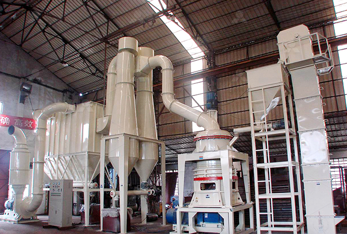
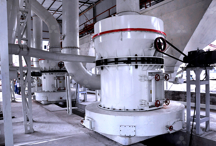
MTW European Type Trapezium Mill
Input size:30-50mm
Capacity: 3-50t/h
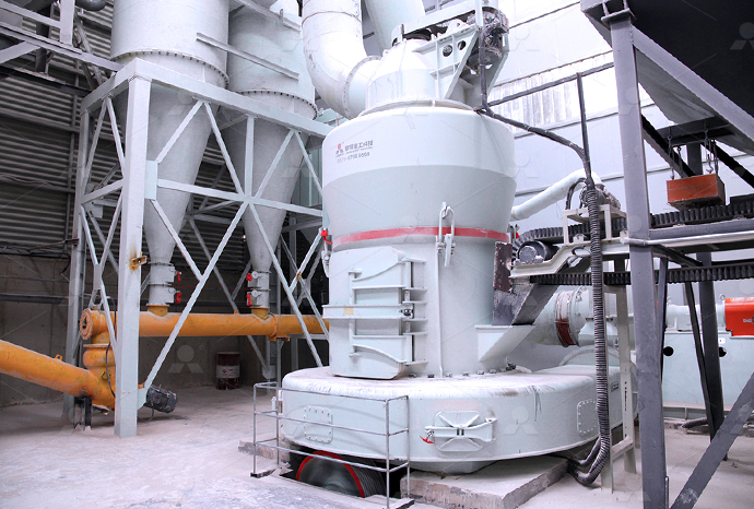
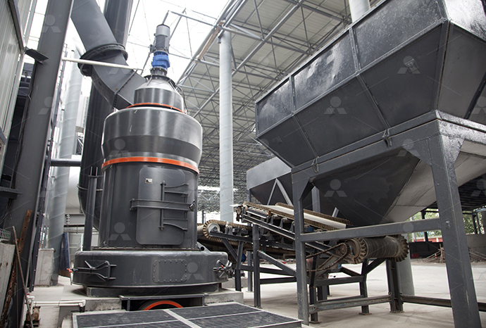
LM Vertical Roller Mill
Input size:38-65mm
Capacity: 13-70t/h
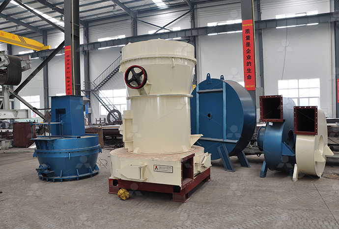
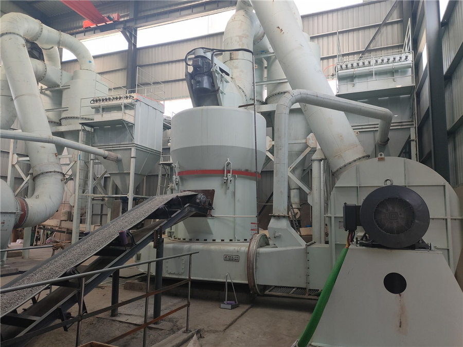
Raymond Mill
Input size:20-30mm
Capacity: 0.8-9.5t/h

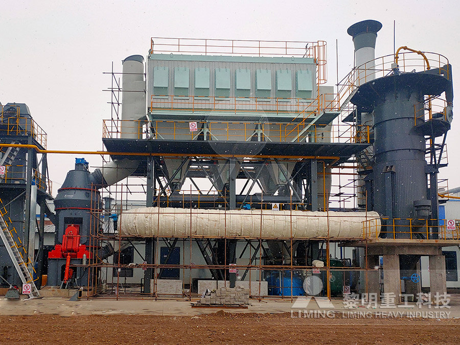
Sand powder vertical mill
Input size:30-55mm
Capacity: 30-900t/h

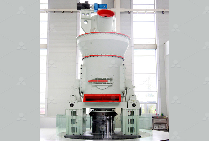
LUM series superfine vertical roller grinding mill
Input size:10-20mm
Capacity: 5-18t/h
MW Micro Powder Mill
Input size:≤20mm
Capacity: 0.5-12t/h

LM Vertical Slag Mill
Input size:38-65mm
Capacity: 7-100t/h

LM Vertical Coal Mill
Input size:≤50mm
Capacity: 5-100t/h
TGM Trapezium Mill
Input size:25-40mm
Capacity: 3-36t/h
MB5X Pendulum Roller Grinding Mill
Input size:25-55mm
Capacity: 4-100t/h

Straight-Through Centrifugal Mill
Input size:30-40mm
Capacity: 15-45t/h
Semiconductor radio circuit diagram
.jpg)
Radio Circuits Practical Analog Semiconductor Circuits
An antenna ground system, tank circuit, peak detector, and headphones are the main components of a crystal radio seen in figure (a) The antenna absorbs transmitted radio Radio systems in which each end can transmit and receive simultaneously Typically two frequencies are used to set up the communication channel Each frequency is used solely for RF Basics, RF for NonRF Engineers Texas InstrumentsThe circuit diagrams included in this manual are for illustration of typical transistor applications and are not intended as constructional informationTransistor Manual Third Edition ECG315 vtdaChapter 9: Semiconductor Radio Design and Components Bipolar and Field Effect Transistors Integrated Circuits Passive Components Frequency Linearity of Tuning Circuits 118 Parts The New Radio Receiver Building Handbook Le Radio di Sophie
Radio Circuits Electrical Engineering Textbooks
An antenna ground system, tank circuit, peak detector, and headphones are the the main components of a crystal radio See Figure above (a) The antenna absorbs transimtted radio signals (b) which flow to ground via the other An antenna ground system, tank circuit, peak detector, and headphones are the the main components of a crystal radio See Figure above (a) The antenna absorbs transmitted radio signals (b) which flow to ground via the other Vol III Semiconductors Practical Analog highly integrated transceiver radio chips that can be programmed to operate at different frequencies The family of products have low cost and high data rate, making them an RF Basics Design Guide Microchip TechnologySix Transistor TR610 Radio Sony Corporation; Tokyo, build 1958, 54 pictures, 7 schematics, 6 semiconductors, Japan, tubes, Broadcast Receiver or past WWSix Transistor TR610 Radio Sony Corporation; Tokyo,
How to Read a Schematic Diagram Part 2 American Radio Relay
schematic — a diagram using electrical symbols that illustrates a circuit plan or "scheme" semiconductor — an electrical component that is made from solid crystal materials, such as 2015年3月27日 How the AM Radio Circuit Works When the reactance (AC resistance) of capacitor C2 is the same as the reactance of the coil L1, resonance occurs at the frequency f=1/2π√(LC) For example, with L1 equal to 300 uH How to Build an AM Radio Receiver Circuit BasicsCircuit Diagram is a free application for making electronic circuit diagrams and exporting them as images Design circuits online in your browser or using the desktop applicationCircuit Diagram A Circuit Diagram MakerAlternative Fullwave Bridge Rectifier Circuit Diagram Remembering the proper layout of diodes in a fullwave bridge rectifier circuit can often be frustrating to the new student of electronics I’ve found that an alternative representation of this Rectifier Circuits Diodes and Rectifiers Electronics
.jpg)
How to Build a Simple Radio Transmitter Circuit: A Diagram
A radio transmitter circuit diagram is a schematic representation of the components required to transmit radio signals It serves as a visual guide for engineers and enthusiasts who are designing or troubleshooting radio transmitters Understanding the essential components of a radio transmitter circuit diagram is important for building a Metal–oxide–semiconductor fieldeffect transistor (MOSFET), showing gate (G), body (B), source (S) and drain (D) terminals The gate is separated from the body by an insulating layer (white) A transistor is a semiconductor device used to amplify or switch electrical signals and powerIt is one of the basic building blocks of modern electronics [1]Transistor WikipediaBuilding a 7 transistor radio circuit diagram is an exciting DIY project that allows you to dive into the world of electronics and create something functional Transistors are semiconductor devices that can amplify and switch electronic signals In a 7 transistor radio, StepbyStep Guide: Building a 7 Transistor Radio Circuit Diagram2017年9月16日 Simple Am Radio Receiver Circuit Homemade How To Build Am Fm Simultaneous Transmitter Using Digital Ic Circuit Diagram Radio And Communication Circuits Part 1 Am Radio Circuit Based On Tda1572 9v Operation 2w Output Radio Circuits Practical Analog Semiconductor Electronics TextbookAm Fm Radio Schematic Diagram
.png)
RF Basics, RF for NonRF Engineers Texas Instruments
SOUND RADIO LIGHT HARMFUL RADIATION VHF = VERY HIGH FREQUENCY UHF = ULTRA HIGH FREQUENCY SHF = SUPER HIGH FREQUENCY EHF = EXTREMELY HIGH FREQUENCY 4G CELLULAR 56100 GHz 24 GHz ISM band ISM bands 315915 MHz UWB 31106 GHz ISM = Industrial, Scientific and Medical UWB = Ultra Wide BandA very simple low power AM FM radio receiver circuit electronic projects can be designed using the TA8122 integrated circuit, manufactured by Toshiba Semiconductor This AM FM radio receiver circuit can be used for portable radio applications or other similar devices TA8122 AM FM radio receiver circuit Electronic Circuits DesignChapter 9: PRACTICAL ANALOG SEMICONDUCTOR CIRCUITS Radio Circuits INCOMPLETE (a) Crystal radio (b) Modulated RF at antenna (c) Rectified RF at diode cathode, without C2 filter capacitor (d) Demodualted audio to headphones An antenna ground system, tank circuit, peak detector, and headphones are the the main components of a crystal radioVol III Semiconductors Practical Analog Semiconductor Circuits Project Overview Welcome to the world of vacuum tube electronics! While not exactly an application of semiconductor technology (power supply rectifier excepted), the audio circuit, illustrated in Figure 1, is used as an introduction Tube Lab Vacuum Tube Audio Amplifier Discrete
.jpg)
Transistor Manual Third Edition ECG315 vtda
Semiconductor Products 1224 West Genesee Street Syracuse, New York Complete Radio Circuit Diagrams 44 Continued following page Page UNIJUNCTION TRANSISTOR CIRCUITS 56 Theory Operation 56 Parameters 2024年11月22日 semiconductor, any of a class of crystalline solids intermediate in electrical conductivity between a conductor and an insulatorSemiconductors are employed in the manufacture of various kinds of electronic devices, including diodes, transistors, and integrated circuitsSuch devices have found wide application because of their compactness, reliability, Semiconductor Definition, Examples, Types, Uses, Materials, 2017年11月4日 Building a twotransistor radio from a circuit diagram is a great way for anyone with a passion for tinkering to bring their creativity to life Radio Circuits Practical Analog Semiconductor Electronics Textbook Reflex Receivers New Kind Of Transistor Radios Show Capability Nano Technology IllinoisCircuit Diagram Two Transistor RadioThe choke passes DC and blocks radio frequencies (RF) from entering the Vbias supply The harmonic filter passes the desired harmonic, say the 3rd, to the output, f3 The capacitor at the bottom of the inductor is a large value, low reactance, to block DC but ground the inductor for RFOscillator Circuits Practical Analog Semiconductor Circuits

What Is RF Integrated Circuit Design? Technical Articles
2020年12月6日 In this overview, we'll take a look at the broad strokes of radio frequency (RF) integrated circuit design RFIC Design Considerations RF IC design, much like niche areas of analog IC design, is often a custom process that is aided by one, or often, many EDA toolsA crystal radio is a simple radio receiver that uses a crystal as the key component to tune in to and receive radio signals It is also known as a crystal set or a crystal receiver Crystal radios were popular in the early days of radio and are still used today as a fun and educational project for amateurs and hobbyistsA Simple FM Crystal Radio Circuit WireBlueprintSchematic and semiconductor identification charts : 657 KB: AM1: Antenna Impedance Meter Complete Manual : 594 KB: AM2: Reflected Power Meter Partial manual : 872 KB: AN10: Mixed Lows Stereo Crossover Schematic and circuit description : 316 KB: AO1: Audio Oscillator Schematic and specifications : 900 KB: AP1800: Deluxe Preamplifier Heathkit Schematic and Manual Archive Vintage Radio InfoA Delco radio schematic diagram provides a visual representation of the electrical circuitry and components within a Delco radio Understanding these diagrams can be crucial for troubleshooting and repairing radio issues In this article, we will explore some key components and terminology commonly found in Delco radio schematic diagrams 1A Guide to Delco Radio Circuit Diagrams
Radio Communication System Block Diagram and types
2 Transmission of Radio Waves: The radio waves from the transmitter are fed to the transmitting antenna (or aerial) from where these are radiated into space The radio waves are electromagnetic waves and have the same general properties These are similar to light and heat waves except that they have longer wavelengthsAll circuit symbols are in standard format and can be used for drawing schematic circuit diagram and layout Home; DIY Electronic It can also be defined as the real earth , when it is applied in radio circuits and power circuits Resistor This is a transistor with a layer of Pdoped semiconductor fixed between two layers of Ndoped Electronic Circuit Symbols Components and Schematic Diagram 2023年7月31日 An integrated circuit (IC) — commonly called a chip — is made out of a semiconductor material called silicon, in which small electronic components called transistors are formed within the silicon and then wired What is an Integrated Circuit (IC)?For more crystal radio circuits, simple onetransistor radios, and more advanced low transistor count radios, see Wenzel [CW1] Regency TR1: First mass produced transistor radio, 1954 The circuit in Figure below is an integrated Radio Circuits Electrical Engineering Textbooks
.jpg)
Continuity Equation in Semiconductor: EEEGUIDE
In general, the current varies with distance within the semiconductor If the current entering the volume at x is I h and leaving at x + dx is I h + dl h, as shown in Fig 632, the number of coulombs per second decreases within the volume and Because of the three effects enumerated above, the hole concentration must change with time, and the total number of coulombs per second A diode is the simplest possible semiconductor device, and is therefore an excellent beginning point if you want to understand how semiconductors work In this article, you'll learn what a semiconductor is, how doping works and how a diode can be created using semiconductors But first, let's take a close look at siliconHow Semiconductors Work HowStuffWorksFirst Steps in Radio How to Read Schematic Diagram Part 2: The first step toward learning the basic theory of this series is to understand circuit diagrams — the a symbols that illustrates a circuit plan or "scheme" semiconductor — an electrical component that is made from solid crystal materials, such as silicon or germanium; modernHow to Read a Schematic Diagram Part 2 American Radio 2022年9月13日 The superheterodyne radio was one of the most successful forms of radio being used almost exclusively as the RF circuit design topology of choice until recent years It works on the principle of heterodyning which simply means mixing The superheterodyne radio receiver mixes the received signal frequency with the frequency of the signal generated by []Working of Superheterodyne Radio Receiver Semiconductor for
.jpg)
Tunnel Diodes World Radio History
blication was prepared for circuit designers RCA devicedesign and circuitapplication gineers It includes theory, device characteristics, circuit diagrams, and detailed design data on these important new semiconductor devices emicon c or and V CC VCC, V DD VDD, V EE VEE, V SS VSS; Every person who is fond of electronics is faced with materials of foreign origin And whether it is a diagram of an electronic device or a specification for a chip, there can be many different designations for power circuits that may well confuse a beginner or radio amateur unfamiliar with this topicWhat is Vcc, Vss, Vdd, Vee in Electronics? WOOPCB2017年9月16日 The Am transistor radio circuit diagram is a representation of all the components found within an AM transistor radio, including the components' circuit connections On the diagram, the components are laid out in order to Am Transistor Radio Circuit Diagram Wiring Digital Specialized Circuits: Additionally, this article explores specialized transistor circuits, including voltage regulators and oscillators These circuits highlight how transistors can be used to stabilize voltage or generate specific waveforms The Ultimate Guide to Understanding Transistor
Schematic Symbols of Electrical and Electronic Components
1: Circuit Diagrams; Circuit diagrams use nationally or internationally recognised symbols to represent the individual components used in the construction of that circuit! They use lines between those components to represent the connections between the components A circuit diagram shows us: The components required to build the circuit!Pulse Circuits 255 25 DC Amplifiers 267 26 DC/DC Converters 281 27 Protection Circuit for Stabilised DC Power Supply 297 28 1000c/s Oscillator and Tuned Amplifier for HF Measurements 303 viii LIST OF CIRCUIT DIAGRAMS Ratio detector using 20A79 110 0A70 as video detector at 30Mc/s 110 0A70 as sound detector in transistor receiver MULLARD TRANSISTOR CIRCUITS World Radio History2024年1月2日 Simple Transistor Circuits for New Hobbyists Many simple transistor configurations like, rain alarm, delay timer, set reset latch, crystal tester, light sensitive switch and many more have been discussed in this article In this compilation of simple transistor circuits (schematics) you will come across many small very important transistor configurations, Build Simple Transistor Circuits – Homemade Circuit ProjectsThe circuit in diagram (c) can actually be used as a crystal set, but some improvements can be made as follows: Circuit of a practical crystal set Detector Loading Unfortunately, connecting anything besides the L and C to the tuned circuit loads it down, reducing performanceThe Crystal Set Radio's Most Basic Receiver Cool386
.jpg)
Tunnel Diode Definition, Symbol, and Working Diode
On the other hand, ptype semiconductor attracts electrons emitted from the ntype semiconductor so ptype semiconductor is referred to as the anode What is a tunnel diode? Tunnel diodes are one of the most significant solidstate electronic devices 2024年1月9日 Hi dear Sir Swagatam Please do a favor and kindly describe me what is the difference of connecting R2 to pin 3 of LM386, as in your diagram ” MIC amplifier circuit using LM386 IC “, or connecting C2 to Pin 3 of LM386 that I seen on a few similar circuit diagram elsewhere Thanks a lot Truly yours NajiehLM386 Amplifier Circuit [Working and Application Circuits]2020年3月4日 One Transistor Radio Circuit Diagram Fm Transmitter Circuit Diagram And Working Bc 547 Transistor Projects 3 Transistor 100 Mreter Fm Transmitter Circuit Soldering Mind Block Transistor Radio Under Repository Circuits 54155 Next Gr Radio Circuits Practical Analog Semiconductor Electronics Textbook Complete Radio CircuitsSchematic Diagram Of A Transistor RadioA very simple low power AM FM radio receiver circuit electronic projects can be designed using the TA8122 integrated circuit, manufactured by Toshiba Semiconductor This AM FM radio receiver circuit can be used for portable radio applications or other similar devices AM FM radio receiver circuit using TA8122 integrated ic